
Installation manual


21
Pin 1 Gray/Black
- Negative (-) ground.
Pin 2 Gray
– 3V positive (+) L.E.D. output.
Pin 3 Gray
– Negative (-) output.
Connector 10 (CN10), 4-Pin (Optional Sensor Input)
This connector provides optional sensor inputs. Most commonly used with proximity and tilt sensors.
Pin 1 Black
– Negative (-) ground.
Pin 2 Black/White
- 2
nd
stage negative (-) input. (Instant trigger)
Pin 3 Red
– 12V positive (+) output.
Pin 4 Grey/White
- 1
st
stage negative (-) input. (Warn away)
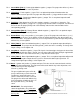
Connector 11 (CN11), 2-Pin (Pre-wired Thermistor)
Plug optional thermistor into this connector to monitor the vehicles’ temperature. It used in conjunction
with Timer Start features along with displaying temperature on two-way LCD’s. To use Timer Start
features review Option Group 2 (page 31). IMPORTANT: New Thermistor plugs are blue 2 pin
connectors on the CM5 series but old white plug Thermistors will still work.
Pin 1 Black
- Thermistor
Pin 2 Black/White
- Thermistor
Connector 12 (CN12), 4-Pin (RS 232 Data Port)
This connector is used for updating control modules via www.compustar.com. You must also use this
port to flash ADS Blade bypass modules. This port provides simple connectivity of Fortin and iDataLink
bypass modules.