
Installation manual


8
You Must Have the OP500 Option Programmer
To set auxiliary outputs on the control module involves the new Programmable Output Connector wires
(POCs). You must choose two odd pin wires on the black 18 pin connector that you are not using. For
example we will use POC 8 and 9.
STEP 1: Plug in OP500 and use the Right or Left Arrow Button to scroll through the menu to POC 8 and POC 9 on LCD Line 1.
STEP 2: Use the Up or Down Arrow Button to change the lower number on LCD Line 2 to 10 – Auxiliary 1 or 11- Auxiliary 2.
STEP 3: Scroll up the menu to Option 4-01 and 4-02 and set the options. Please see the Option Table for details.
STEP 4: The Pro control modules have a secure auxiliary option 4-05. This requires you to tap button 4 before you tap button 2
for Aux 1 or button 3 for Aux 2. On 1-Way remotes you must hold the Trunk and Key/Start buttons for 2.5 seconds then tap the
Trunk button for Aux 1 or the Key/Start button for Aux 2.
STEP 5: If you need to change the time settings of the outputs go to AU1 or AU2 on the OP500. LCD Line 2 is the timed output.
STEP 6: Hold the “W” Write button for 3 seconds to set all the options.
Tach Sensing
The default engine sensing mode is tach. In cold weather climates we recommend using an injector wire
verses a coil wire for tachometer sense. There are new features that adjust tach reading methods on
option 2-01. IMPORTANT: The remotes must be coded prior to setting up tach sensing. Firstech
recommends using a digital multimeter to test for tach.
STEP 1: Start the vehicle with the key. Allow time for the engine to idle down.
STEP 2: Test wire and make connection. At idle the tach wire should test between 1 to 4 Volts AC. As
the vehicle RPM’s increase the voltage on the meter will also increase. Always solder tach connections.
STEP 3: Learn tach. While the vehicle is at idle, hold the foot brake and press and hold the remote start
button on the remote control for 2.5 seconds.
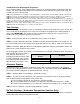
The parking lights will flash once and the siren will chirp once to confirm a good tach signal. The parking
lights will flash three times and the
siren will chirp three times to
indicate the tach did not learn. Two
seconds following the three flashes,
the number of parking light flashes
will indicate the cause of the error:
Alternator Sensing
Alternator sensing is an alternative method the remote start can utilize to determine if the engine is
running. This is different than the no tach sensing mode so a connection must be made. IMPORTANT:
The remotes must be coded prior to setting up alternator sensing.
STEP 1: Change Option 2-10 to setting 2 - Alternator sensing.
STEP 2: Test wire and make connection. The stator wire is found at the vehicle’s alternator. Change
your multimeter to DC voltage before testing for this wire.
A. At rest, with the ignition off, the stator wire should test 0V DC.
B. Turn the ignition to the run position. The stator wire should now test between 4 – 6V DC.
C. Start the vehicle with the key. The stator wire should now test between 12 – 14V DC at idle.
STEP 3: Process complete – no further programming is required.
No Tach Sensing – (Automatic Transmission Vehicles Only)
No tach sensing is an alternative engine sensing mode. No tach sensing does not require a connection
to the vehicle other than the main ignition harness.
Number of Parking Light
Flashes
Tach Error
1 Option 2-10 is not in default setting 1
2 Key is in the off position
3 Bad tach signal. Find a different wire.