CM6000 Alarm and Starter Installation Manual MODEL: RF-2W900FM-5PT Firstech, LLC. 21911 68th Ave S. Kent, WA 98032 Phone. 888-820-3690 Fax. 206-957-3330 Please visit www.firstechonline.
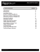
Alarm and Starter System CM6000 Install Guide Table of Contents Introduction Kit Contents Installation Basics Remote Programming Routine Placement and Use of Components Placement and Use of Components Common Procedures Wiring Descriptions Option Programming Tables Option Menu Descriptions Special Option Groups 1 & 2 Option Programming Troubleshooting Frequently Asked Questions Technical Support Contacts Copyright 2009 Firstech, LLC. www.firstechonline.com | www.compustar.
Alarm and Starter System CM6000 Install Guide Copyright 2009 Firstech, LLC. www.firstechonline.com | www.compustar.
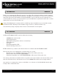
Alarm and Starter System CM6000 Install Guide www.firstechonline.com | www.compustar.com Introduction CM6000 Thank you for purchasing this Firstech system for your vehicle. The following installation manual is intended for experienced and authorized Firstech technicians. We highly recommend that you contact your local Firstech dealer and seek professional installation. Call 888-820-3690 or visit our websites at www.compustar.com or www.firstechllc.com to locate your nearest dealer.
Alarm and Starter System CM6000 Install Guide Installation Basics www.firstechonline.com | www.compustar.com CM6000 If you are new to installing Firstech Series Remote Starts and / or Alarms, we highly recommended that you thoroughly review this manual to installing your first unit. Key Points to Consider Before Installation: You must code remotes to this system before anything will function. Program remotes by cycling the ignition ON / OFF five times within seven seconds and tap button 1 (0.
Alarm and Starter System CM6000 Install Guide Remote Programming Routine www.firstechonline.com | www.compustar.com CM6000 IMPORTANT: Any and all remotes must be coded to the control module prior to performing any and all operations. Remotes excluding 2WSSR-Pro STEP 1: Activate programming mode by manually turning the vehicle’s key between the Ign On and Off (or the Acc & On positions) five times within 7 seconds. The vehicle’s parking lights will flash once with the successful completion of this step.
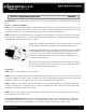
Alarm and Starter System CM6000 Install Guide Placement and Use of Components www.firstechonline.com | www.compustar.com CM6000 IMPORTANT: The placement and use of components are critical to the performance of this system. Antenna and Cable Firstech antennas are calibrated for horizontal installation at the top of the windshield. The cable that connects the antenna to the control module must be free from any pinches or kinks.
Alarm and Starter System CM6000 Install Guide Placement and Use of Components www.firstechonline.com | www.compustar.com CM6000 Firstech Shock Sensor For best results mount the shock sensor by zip tying it to the vehicles main ignition harness. There is a small dial on the sensor that ranges from Off to 10. The higher the number on the dial the greater sensitivity of impact. A small adjustment to the dial can make a significant difference in sensitivity for both 1st and 2nd stages.
Alarm and Starter System CM6000 Install Guide www.firstechonline.com | www.compustar.com Jumper 3 (Parking Light to Trunk Output) Determines the output type (not polarity) of the green/white wire on connector one (CN1). In the default position it provides a positive (+) parking light output. To change to a positive (+) trunk output move the jumper. A negative (-) parking light output is found on connector three (CN3) and a negative (-) trunk output is found on connector four (CN4).
Alarm and Starter System CM6000 Install Guide www.firstechonline.com | www.compustar.com Alternator Sensing Alternator sensing is an alternative method the remote start can utilize to determine if the engine is running. This is different than the no tach sensing mode so a connection must be made. IMPORTANT: The remotes must be coded prior to setting up alternator sensing. STEP 1: Change Option 2-10 to setting 2 - Alternator sensing. STEP 2: Test wire and make connection.
Alarm and Starter System CM6000 Install Guide www.firstechonline.com | www.compustar.com Installation Requirements 1. The vehicle’s door triggers must be connected to the control module. Prior to making final connections, test the factory door triggers to ensure that they are functioning properly. 2. The vehicle’s emergency/parking brake wire must be connected to the control module. The proper vehicle wire usually provides a negative (-) trigger while the emergency / parking brake is set. 3.
Alarm and Starter System CM6000 Install Guide www.firstechonline.com | www.compustar.com The new CM6 Series the Blade connector has a locking tab. Non-locking tab blade harnesses will work but you MUST TAKE CARE TO NOT PLUG THE HARNESS IN UPSIDE DOWN. Make sure the two notches on the top of the harness face the top (CM and barcode sticker side) of the brain. When looking at the wire side of the harness the two notches must be at the top of the plug. Blade system includes: 1.
Alarm and Starter System CM6000 Install Guide www.firstechonline.com | www.compustar.com There are two wires coming off of the relay; yellow-black and yellow. To utilize the anti-grind or starter- kill features, the vehicles starter wire must be cut in half, otherwise, cut the relay out of the harness and connect the yellow (Pin 6) directly to the vehicles’ starter wire. The starter kill/anti grind relay has a thin 24 guage blue wire.
Alarm and Starter System CM6000 Install Guide www.firstechonline.com | www.compustar.com Pin 6 Green/White – This is a dual-purpose wire that features selectable functionality thru the trunk/light jumper on the control module. It is either a positive (+) parking light output or positive (+) trunk output. This wire carries a 10 amp fuse. Default - Parking light positive (+) output. The proper vehicle wire will test (+) 12V when the parking light switch is in the on position.
Alarm and Starter System CM6000 Install Guide www.firstechonline.com | www.compustar.com Pin 8 Violet/Black - Trunk negative (-) input. This is an optional input that will monitor when the vehicle’s trunk has been opened. The proper wire will provide a (-) trigger while the trunk is open. Pin 9 White/Black [POC 4] - 2nd Accessory 250mA negative (-) output. This output can be used to trigger the pre-wired relay located on the main ignition harness. Pin 10 Red/White - Door trigger input.
Alarm and Starter System CM6000 Install Guide www.firstechonline.com | www.compustar.com Pin 17 White [POC 8] - Horn honk 250mA negative (-) output. This is an optional output that will pulse the factory horn. The proper wire will show ground (-) while the horn is sounding. To change horn output settings, review Options 3-8 and 3-9. Pin 18 Gray/Black – Hood Pin negative (-) input. This input is a safety shut down and alarm trigger.
Alarm and Starter System CM6000 Install Guide www.firstechonline.com | www.compustar.com Connector 6 (CN6), 4-Pin (RS 232 Data Port) This connector is used for updating control modules via www.firstechonline.com. You must also use this port to flash Blade bypass modules. This port provides simple connectivity of Fortin and iDataLink bypass modules. Connector 7 (CN7), 3-Pin (Pre-wired Valet/Programming Switch) Pin 1 Gray/Black - Negative (-) ground. Pin 2 Gray – 3V positive (+) L.E.D. output.
Alarm and Starter System CM6000 Install Guide www.firstechonline.com | www.compustar.com Connector 10 (CN10), 6-Pin to 6-Pin (Pre-wired Antenna Cable) Connect your antenna cable to this port. You can only use 6 to 6 pin antenna cables. 4 to 4 or 4 to 6 Pin antenna cables do not work. Do not use both Connector 9 and Connector 10 at the same time. Pin 1 Yellow - RX input. This wire receives the signal from remote. Pin 2 White - TX output. This wire transmits the signal to remote.
Alarm and Starter System www.firstechonline.com | www.compustar.com CM6000 Install Guide Connector 14 (CN14), 4-Pin (Optional Sensor Input) This connector provides optional sensor inputs. Most commonly used with proximity and tilt sensors. Pin 1 Black – Negative (-) ground. Pin 2 Black/White - 2nd stage negative (-) input. (Instant trigger) Pin 3 Red – 12V positive (+) output. Pin 4 Grey/White - 1st stage negative (-) input.
Alarm and Starter System www.firstechonline.com | www.compustar.
Alarm and Starter System www.firstechonline.com | www.compustar.
Alarm and Starter System www.firstechonline.com | www.compustar.
Alarm and Starter System CM6000 Install Guide www.firstechonline.com | www.compustar.com 1-04 Double Pulse Unlock - If enabled, this option will cause the system to double pulse the unlock output. This option is used on a majority of Toyota vehicles. The first unlock pulse disarms the alarm, and the second pulse unlocks the doors. 1-05 Rearm Output - These optional settings change the event trigger on the orange rearm wire. 1-06 Reservation Lock - Manual transmission only.
Alarm and Starter System CM6000 Install Guide www.firstechonline.com | www.compustar.com 2-01 Tach Sensing Method – This option will adjust the method at which tach is read by the module. At de fault this option will minimize overcrank during remote start. 2-02 Turbo Mode – This option will adjust the run time after Turbo mode has been engaged. The e-brake and door trigger inputs must be connected and the option must be turned on through the remote for turbo timer to engage.
Alarm and Starter System CM6000 Install Guide www.firstechonline.com | www.compustar.com 2-09 Temperature of Hot Starting – Works in conjunction with Options 2-05 and 2-06. See the option table for available temperatures. 2-10 Engine Sensing – Review the “Common Procedures” section for complete explanations on the four engine sensing modes. 2-11 Runtime Extension – This option resets the engine run countdown before the vehicle shuts off for either the remote start or turbo timer.
Alarm and Starter System CM6000 Install Guide www.firstechonline.com | www.compustar.com 3-07 Siren Duration (Upon Alarm Trigger) - This option changes the time that the siren sounds during alarm trigger. The available options are 30, 60, and 120 seconds. It will also sound chirps for 20 seconds as a fourth option. 3-09 Horn Output When Alarm is Triggered - This changes the behavior of the white horn wire when the alarm is triggered.
Alarm and Starter System CM6000 Install Guide www.firstechonline.com | www.compustar.com 4-01 Aux 1 Output - This option determines the duration of the auxiliary 1 output. Setting IV allows the out put duration to be set for a specific length of time. 4-02 Aux 2 Output - This option determines the duration of the auxiliary 2 output. Setting IV allows the out put duration to be set for a specific length of time.
Alarm and Starter System CM6000 Install Guide www.firstechonline.com | www.compustar.com 4-08 Extended Accessory After Ignition Shutoff – This option keeps the Accessory wire powered up after the ignition is shut off. This can be used to keep the radio turned on even after the key is removed from the ignition (similar to GM vehicles). 4-09 Glow Plug or Key Sense – Default setting sets the wire as a glow plug input. Option setting 2 changes the wire to a key sense input.
Alarm and Starter System CM6000 Install Guide www.firstechonline.com | www.compustar.com Special Option Groups 1 & 2 CM6000 IMPORTANT: The OP500 is required to change settings in Special Option Groups 1 and 2. Special Option Group 1 1 Diesel Timer – Option 2-03 must first be set to setting 2. This special option allows a specific wait to start time (in seconds) to be programmed. This prevents the need for a timer relay and eliminates a con nection to the “wait to start” wire.
Alarm and Starter System www.firstechonline.com | www.compustar.com CM6000 Install Guide At the end of menu 4, if diesel mode or auxiliary setting functions were enabled – or if any of the auxiliary outputs were set to “Program”, the duration of these settings can now be adjusted. Following the auxiliary and diesel settings (if selected), the POC options will be displayed on the OP500. The POCs can be set between 0 (default) and 19.
Alarm and Starter System www.firstechonline.com | www.compustar.com CM6000 Install Guide Hold Trunk + Key/Start for 2.5 seconds Hold Trunk + Key/Start for 2.5 seconds Hold Trunk + Key/Start for 2.5 seconds Hold Trunk + Key/Start for 2.5 seconds Tap Lock Button Tap Lock Button Tap Lock Button Tap Lock Button Select Option 4 Select Option 3 Select Option 2 Select Option 1 Wait for corresponding parking light flash and/or siren chirp before selecting the option Lock + Unlock for 2.
Alarm and Starter System www.firstechonline.com | www.compustar.com CM6000 Install Guide Troubleshooting CM6000 Remote Start Error Codes If the remote start fails to start the vehicle, the parking lights will flash three times immediately.
Alarm and Starter System CM6000 Install Guide www.firstechonline.com | www.compustar.com I am trying to program the control module with the OP500 Option Programmer and it flashes “ER 01” when I plug it in to the antenna cable. What should I do? A: Make sure that the system is not locked/armed. The last thing to check is the antenna cable or antenna extension cable – make sure this is not damaged. If you need to, try another cable. When the OP500 is working properly, it will read “success good.
Alarm and Starter System CM6000 Install Guide www.firstechonline.com | www.compustar.com The vehicle will lock and unlock, but will not remote start or flash the parking lights. A: The system is in valet mode. Tap buttons (I) + (III) for 0.5 seconds while the key is in the on position. Whenever I try to arm the vehicle, it chirps the siren 3 times and will not arm. A: Check the hood and trunk trigger inputs. When I turn the ignition on the parking lights flash 3 times and/or siren chirps 3 times.
Alarm and Starter System CM6000 Install Guide Technical Support Contacts www.firstechonline.com | www.compustar.com CM6000 Firstech technical support is reserved for authorized dealers only. Monday - Friday: 888-820-3690 (8:00 am – 5:00 pm Pacific Coast Time) Email: support@compustar.com Web: Register at: www.firstechonline.com click on “Authorized Tech” Wire Diagrams Click on the “Installogy Access Client” link found on your desktop.