USER’S GUIDE One-Way AM Remote R500A / Alarm Controller CM1000A One-Way AM Remote R500A FCC ID :O44J1WENR This device complies with Part 15 of the FCC Rules. Operation is subject to the following two conditions: (1) This device may not cause harmful interference, and (2) This device must accept any interference received, including interference that may cause undesired operation.
User’s Guide User’s Guide Table of Contents Safety information Page 3 Remote Description: R500A Page 3 Remote Button Functions Page 4 Remote Coding Procedure Page 5 Locking and Unlocking the Doors Page 5 Arming and Disarming System Page 6 Trunk Release Page 6 Panic Mode Page 6 Valet Mode Page 7 Optional Programmable Features Ignition Controlled Door Locks Page 7 Passive Locking Page 8 Starter or Ignition Kill Page 8 Anti Jacking Mode Page 9 Mute Mode Page 9 Door Open Indicator
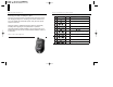
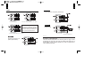
Safety Information 4 Re m ote Button Functions Button Servicing your vehicle or loaning it to others Servicing your vehicle or loaning it to others When servicing the vehicle, like changing/checking the oil, or loaning your vehicle to someone who may not be familiar with Compustar systems, it may be best to put the system in valet mode. Press Function 1 0.5 sec Lock 2 0.5 sec Unlock 3 0.5 sec Siren Chirps - on/off (while arming/disarming) 4 0.
5 6 Remote Coding Procedure Arming and Disarming the System The remote must be coded to the system installed in the vehicle before it can be operated in any way. Listed below is the remote coding procedure, please read through the directions before beginning. To arm the alarm, hold the button down until the LED on the remote stops flashing. To disarm the alarm, hold the button down until the LED on the remote stops flashing.
7 Valet Mode When in Valet mode, locking and unlocking the vehicle doors will be the only operations available through the remote, the system will not arm the alarm. The siren will be muted at this time as well. Use Valet mode mainly for the reasons described in the “Safety Information” section of this manual. To activate Valet mode, tap the and buttons simultaneously for a split second. Do the same again to remove the system from Valet Mode.
10 9 In a manual transmission vehicle, if the ignition is powered up, the vehicle can be compression or “bump” started without using the starter. Disabling the ignition will keep the vehicle from starting. Anti-Jacking Mode To use Anti-Jacking mode, the starter kill relay must be rewired to an ignition kill, and Anti-Jacking mode must be turned on in the programming options.
11 Installation Tips and Recommendations 1. Precautions to prevent locking yourself out Lower the window in one or more doors before beginning installation. This allows you to reach inside the vehicle in case you accidentally lock the keys inside the vehicle during the course of installation. Remotes are not programmed to the system so you will have to program them before operating the system. See page 5 for details. 2.
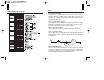
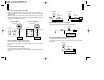
13 CM1000A Wiring Diagram 14 CON 1 Red : 12v Constant Input Constant 12-volt (+) positive power input for the control module. This wire must be connected to a constant 12-volt (+) positive source. The proper wire will test 12-volt (+) positive with the key in the off position, while key is in the on position and during crank. Violet : (+) Parking Light Output Connect this wire to the (+) positive parking light wire generally at the parking light switch or behind the fuse box.
15 16 CON 2 Method 2 Positive Trigger Door Lock System (W/O Actuator) < Circuit diagram > < Circuit diagram during unlock output > The lock and unlock outputs of the CM1000A are actually two pre-wired relays that can be configured in the three following ways listed below. When connecting to a constant 12v+ source, you must fuse the connection. Method 3 External Actuator < Circuit diagram during lock output > Method 1 Negative Trigger Door Lock System (W/O Actuator) < External Actuator > CON 3 No.
17 18 No.2 Blue : Negative Starter Kill Output 250mA (-) negative output when armed. This wire will provide a (-) negative output when system is locked and armed, and is pre-wired to the starter kill relay. (Note:This wire can also be used to trigger after-market L.E.D. kits and other after-market accessories. Output must be diode isolated when used to trigger after-market accessories.) .... Starterkill Mode ...
19 20 No.7 Black/White : Negative Input for Optional Sensor When installing additional sensors, use this wire as the input wire to the alarm module for those sensors. When connecting more than one sensor to any input wire, you must diode isolate the output wires of each sensor. Otherwise, they could back feed into each other, causing false alarms or sensor damage. CON 4 No. 1 Black : L.E.D. Ground No. 2 Black / White : L.E.D. 3v Positive Option Menu Features 1 No. 1 Black No. 2 White No. 3 Red No.
21 22 4. 30 sec Passive Relock With this option enabled, after disarming the system with the remote, the system will relock the doors and arm the alarm after 30 seconds if a door has not been opened. At 10 and 20 seconds after the disarm command was given, the siren will chirp once to indicate that the alarm is about to rearm. At 30 seconds after, the siren will chirp once, and the system will arm the alarm. If you wish to stop this process, you must open a door within 30 seconds of disarming the alarm.