CM4200DX Remote Starter INSTALL GUIDE WWW.COMPUSTAR.COM I.
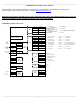
CM4200-DX INSTALLATION GUIDE TABLE OF CONTENTS CM4200-DX Wiring Diagram -----------------------------------------------------------------------------------------Detailed Wiring Guide and Descriptions -----------------------------------------------------------------------------Dip Switches -------------------------------------------------------------------------------------------------------------Little Green Loop ----------------------------------------------------------------------------------------------
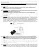
________________________________________________________________________________________________ CM4200-DX STARTER CONTROL MODULE This manual is for professional installers. If you have any questions please call CompuStar Tech Support @ 888.820.3690 (8 am to 5 pm Pacific Time) or email: support@compustar.com Important Note: Before you make all your wire connections and connect the additional items please review the Option Programming Tables and the descriptions at the end of this manual.
_______________________________________________________________________________________________ DETAILED WIRING GUIDE Important Note: Before you make all your wire connections and connect the additional items please review the Option Programming Tables and the descriptions at the end of this manual. CONNECTOR 1 (CN1) Pin 1 Red - Constant 12-volt (+) positive power input for the control module. This wire must be connected to a constant 12-volt (+) positive source.
starter wire will need to be cut. The yellow wire from pin 87a on the starter interrupt relay will go to the starter side of the vehicles starter wire. The yellow/black wire from pin 30 of the starter interrupt relay will go to the key side of the vehicles starter wire.) Pin 7 Green and Red - Ignition output and input. This wire must be connected to the vehicles ignition to power up all accessories and to trigger remote programming.
Pin 7 *White/Black - 2nd Accessory 250mA (-) negative output. This is an optional output that will provide a (-) negative output while the accessory output is triggered. Pin 8 Red/White - Door trigger input. This wire monitors (-) negative or (+) positive trigger door-pins. The proper wire will provide a (-) negative trigger or a (+) positive trigger only when the doors are opened. You will need to test the wire for proper polarity and set door dip switch on the control module for the proper polarity.
trunk release.) Pin 3 Orange/Black - 2nd Unlock 250mA (-) negative output. This wire is an optional output that will provide a (-) negative pulse output for driver’s priority door lock. (Note: This feature will require additional relays and programming.) Pin 4 Blue - Unlock 250mA (-) negative output. This wire will provide a (-) negative pulse output during unlock and disarm. (Note: Positive and reverse polarity will require additional relays.) Pin 5 Blue/Black - Lock 250mA (-) negative output.
Switch 2 sets the polarity of input for the brown/white key sense or glow plug wire on CN3, Pin 10. This switch also is set in the Option Programming Menu. (Option 4-9) In the default position switch 2 should be down and set for positive (+) Glow Plug input. When you change Option 4-9 to setting 2 the brown/white wire now becomes a Key Sense input. This is used to prevent Passive arming or Setting Reservation Mode (Manual Transmission) while the key is still in the ignition.
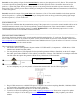
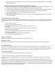
6. You will need to first identify what COM port your USB device is set up to use. To do this, Right-click on "My Computer" and go to "Properties". Once the properties window is on the screen, click the "Hardware" tap at the top of the window. Then in the main body of the window, click on the Device Manager" button. Under "Ports (COM & LPT)" There should be a device called "USB Serial Port (COM?)", the number that is in place of the question mark is your selected com port.
6. After a few seconds you will hear two relay “clicks” and see two parking light flashes and remote coding has been completed. Remote Coding with Secure Valet Switch – Option 3-10, Setting III To use the Secure Valet Switch you must program Option 3-10, Setting III. The Secure Valet default code is 33. 1. Hold down valet switch for 1.5 seconds. LED on switch will begin to flash rapidly. 2. Tap the button on the switch to enter first number of 2-digit code. LED will flash the first number slowly. 3.
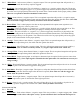
Number of Parking Light Flashes 1 2 3 Tach Error Option 2-10 not in default setting 1 Car key in off position No signal or not fast enough ________________________________________________________________________________________________ ALTERNATOR SENSING The alternator sensing is alternative engine sensing input. This is not voltage sensing. To use alternator sensing the engine sense input (yellow/black CN3, Pin 14) must be connected to the stator wire on the alternator. This will be a small gauge wire.
When trying to remote start the vehicle you may experience an error.
Lock+Key for 2.5 sec. then Lock+Key for 2.5 sec. Menu 4 2. Selecting the Specific Option Once you select the Option Menu in Step 1 you must scroll through that menu for the specific option. [Hold the Trunk+Key Buttons for 2.5 seconds] You will hold the Trunk+Key Buttons for 2.5 seconds each time you want to move down 1 position in the option menu. The parking lights will also flash and siren chirp once.
[III] for a split (0.5) second for optional setting 3 [IV] for a split (0.5) second for optional setting 4 Resetting to Factory Defaults To reset the options in a menu, enter the menu. (Step 1) After the parking lights flash and/or siren chirps tap Button III three times. The siren will chip and parking lights flash three times. The options in that menu will reset to the default settings. III.
To change the option number you wish to program, use the left and right arrow keys on the OP-500, it will scroll through the options available in menu 1 and then move to menu 2, then 3 and 4. At the end of menu 4, if you have turned on diesel mode or the channel expander, or set any of the auxiliary outputs to “Program”, you will have the option to program the duration of the diesel timer and/or auxiliary outputs. After the aux and diesel settings (if selected), the POC options will be displayed.
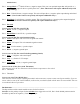
1-7 Unlock / Disarm With Trunk Release 1-8 Locking while in Passive Arming Unlock, Factory Disarm, and Trunk Release Passive locking w/ Passive Arming Factory Disarm, Trunk Release Only No Passive Locking w/ Passive Arming Trunk Release Only V V V V V V 1-9 Ignition controlled door locks Off On RPM Locks (Tach Sensing Mode Only) V V V 1-10 Auto Relock (If a door is not opened within this amount of time.
5 AUX4 output time 1 ~ 100 V V V 6 AUX5 output time 1 ~ 100 V V V 7 AUX6 output time 1 ~ 100 V V V 8 AUX7 output time 1 ~ 100 V V V SPECIAL OPTION GROUP #2 Applicable To Feature Programmable Output Connector Setting Value 0[Default] CM4000 CM4200-DX CM4300 V 1~12 1 POC #1 2nd LIGHT V V 2 POC #2 2nd START V V 3 POC #3 2nd IG1 V V 4 POC #4 2nd ACC V V 5 POC #5 STATUS V V 2nd Light[1], 2nd Start[2], 2nd IG1[3], 2nd Acc[4], Status Out[5], Rearm Out[6], D
This option setting will set the unlocking/disarming of the control module during the trunk release through the remote. Setting 2 keeps the doors locked, disarms the alarm and opens trunk. Setting 3 opens the trunk only. 1-8 Locking while in Passive Arming This option determines the behavior of the locks during passive arming. After 30 seconds the vehicle will either lock and arm or not lock and just arm. 1-9 Ignition controlled door locks: Tach sensing mode must be used for this feature to work.
4) Option 2-8 (Temp 32°F) on setting 4 5) Set the reservation time at 7 AM (see User’s guide) 6) Turn on Timer Mode on the 2-Way remote. (See Remote User’s Guide) 2-7 Remote Start Runtime This option sets how long the vehicle will remote start and run for. Default setting 1 is 15 minutes. Setting 2 is 25 minutes. Setting 3 is 45 minutes and Setting 4 is 3 minutes. 2-8 Temperature of Cold Starting This option sets the temperature at which the vehicle will remote start when setting 2-5 and 2-6 are set.
3-4 Anti-Grind/Starter-Kill relay With this option on the default setting, the starter-kill relay will act as an anti-grind circuit only. It will not disable the starter when the system is locked/armed. On setting 2, the starter-kill relay will act as an anti-grind and starterkill circuit. Setting 3 is the same as 2, but a passive starter-kill is activated 45 seconds after the vehicle is turned off or disarmed.
This option controls the trigger of the Aux output. These are optional event triggers. Default setting triggers Aux 1 by the remote. Setting 2 triggers Aux 1 by remote and arming of the system. Setting 3 triggers Aux 1 by remote and disarming of the system. Setting 4 triggers Aux 1 through panic of the system. 4-4 Aux 2 output Control This option controls the trigger of the Aux output. These are optional event triggers. Default setting triggers Aux 2 by the remote.
TO THE MAXIMUM EXTENT ALLOWED BY LAW, ANY AND ALL WARRANTIES ARE EXCLUDED BY THE MANUFACTURER AND EACH ENTITY PARTICIPATING IN THE STREAM OF COMMERCE THEREWITH. THIS EXCLUSION INCLUDES BUT IS NOT LIMITED TO, THE EXCLUSION OF ANY AND ALL WARRANTY OF MERCHANTABILITY AND/OR ANY AND ALL WARRANTY OF FITNESS FOR A PARTICULAR PURPOSE AND/OR ANY AND ALL WARRANTY OF NON-INFRINGEMENT OR PATENTS, IN THE UNITED STATES OF AMERICA AND/OR ABROAD.