Version 6.
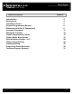
Alarm System CM6300 Install Guide Table of Contents Introduction Kit Contents Installation Basics Remote Programming Routine Placement and Use of Components Common Procedures Wiring Descriptions Option Programming Tables Option Menu Descriptions Special Option Groups 1 & 2 Option Programming Troubleshooting Frequently Asked Questions Technical Support Contacts Copyright 2011 Firstech, LLC. www.firstechonline.com | www.compustar.
Alarm System CM6300 Install Guide Copyright 2011 Firstech, LLC. www.firstechonline.com | www.compustar.
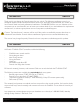
Alarm System CM6300 Install Guide Introduction www.firstechonline.com | www.compustar.com CM6300 Thank you for purchasing this Firstech system for your vehicle. The following installation manual is intended for experienced and authorized Firstech technicians. We highly recommend that you contact your local Firstech dealer and seek professional installation. Call 888-820-3690 or visit our websites at www. compustar.com or www.firstechllc.com to locate your nearest dealer.
Alarm System CM6300 Install Guide Installation Basics www.firstechonline.com | www.compustar.com CM6300 If you are new to installing Firstech Series Remote Starts and / or Alarms, we highly recommended that you thoroughly review this manual to installing your first unit. Key Points to Consider Before Installation: You must code remotes to this system before anything will function.
Alarm System CM6300 Install Guide Remote Programming Routine www.firstechonline.com | www.compustar.com CM6300 IMPORTANT: Any and all remotes must be coded to the control module prior to performing any and all operations. STEP 1: Activate programming mode by manually turning the vehicle’s key between the Ign On and Off (or the Acc & On positions) five times within 7 seconds. The vehicle’s parking lights will flash once with the successful completion of this step.
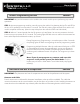
Alarm System CM6300 Install Guide Placement and Use of Components www.firstechonline.com | www.compustar.com CM6300 RPS Touch and RPS (Remote Paging Sensor) The RPS is an optional feature. The car call/RPS feature uses a small sensor that is mounted on the inside of your windshield. Important: When using the RPS Touch, you cannot use the LED port or Secure Valet Switch.
Alarm System CM6300 Install Guide www.firstechonline.com | www.compustar.com Placement and Use of Components CM6300 2 Way LCD remote paging To page a 2 Way LCD remote just tap the ‘Red Circle’ twice. Touch Panel Sensitivity To change touch sensitivity open the driver’s door, hold the button on the back of the RPS Touch until the LEDs go out. Release button and tap again. The number of solid LEDs represent sensitivity of touch, 1 being the lowest, 5 the highest.
Alarm System CM6300 Install Guide Placement and Use of Components www.firstechonline.com | www.compustar.com CM6300 STEP 5: The LED on the RPS will confirm your first number by flashing BLUE slowly. Once the LED begins to flash rapidly in BLUE, enter your second number by repeating step 4. STEP 6: Repeat steps 4 & 5 to enter all four numbers. STEP 7: Turn the ignition OFF - the RPS disarm/unlock passcode is now programmed. Follow steps 3 – 5 to enter your disarm/unlock code.
Alarm System CM6300 Install Guide www.firstechonline.com | www.compustar.com Placement and Use of Components CM6300 DAS Sensor The DAS sensor monitors forward movement for remote starting manual transmissions, dual stage impact, and auto adjusting tilt sensor. Follow the steps below to properly setup your DAS sensor. Installing Your DAS STEP 1: Set Option 4-12 to Setting 2 STEP 2: Set switch 1 and 2 on the side of the DAS. *See below for explanation or switches.
Alarm System CM6300 Install Guide www.firstechonline.com | www.compustar.com Thermister (Temperature Sensor) Every 2 Way LCD Firstech RF kit includes an optional thermister, which must be plugged into the 2 pin port of the control module for use. This plug is blue on the CM6300.
Alarm System CM6300 Install Guide www.firstechonline.com | www.compustar.com STEP 4: The control modules have a secure auxiliary option 4-05. This requires you to tap button 4 before you tap button 2 for Aux 1 or button 3 for Aux 2. On 1-Way remotes you must hold the Trunk and Key/Start buttons for 2.5 seconds then tap the Trunk button for Aux 1 or the Key/Start button for Aux 2. STEP 5: If you need to change the time settings of the outputs go to AU1 or AU2 on the OP500. LCD Line 2 is the timed output.
Alarm System CM6300 Install Guide www.firstechonline.com | www.compustar.com Connector 1 (CN1), 4-Pin Pin 1 Red - Constant 12V positive (+) power input. This wire must be connected. The proper vehicle wire will test (+) 12V at all times while the key is in the off position, the on position and during crank. Pin 2 Green/White – This is a dual-purpose wire that features selectable functionality thru the trunk/light jumper on the control module.
Alarm System CM6300 Install Guide www.firstechonline.com | www.compustar.com Connector 3 (CN3) , 20 Pin Blade Connector - New Generation This connector is used only if you are installing a Blade-AL or Blade-TB. The wiring harness for this connector also comes with the Blade cartridge. Please refer to the Blade install guide for wire description. The new generation 20 pin Blade connector now has a locking tab. The old connector with out a locking tab is compatible but you must modify the connector.
Alarm System CM6300 Install Guide www.firstechonline.com | www.compustar.com Pin 11 Black [POC 5] – Auxiliary 2 250mA negative (-) output. This is an optional output that will provide a programmable output to trigger sliding doors, power windows or whatever other features you’d like. Pin 12 Brown/White - This wire looks for key sense negative (-) input. The proper wire will show a (-) trigger only when the key is in the ignition.
Alarm System CM6300 Install Guide www.firstechonline.com | www.compustar.com Connector 5 (CN5), 6-Pin Pin 1 Not used Pin 2 Violet/White - Trunk release 250mA negative (-) output. This is an optional output that will release the trunk. Use CN1, Pin 2 if the vehicle is equipped with a (+) trunk release. System will unlock doors and disarm alarm prior to trunk release. Pin 3 Orange/Black - 2nd Unlock 250mA negative (-) output.
Alarm System CM6300 Install Guide www.firstechonline.com | www.compustar.com Connector 7 (CN7), 4-Pin to 4-Pin or 6-Pin (Pre-wired Antenna Cable) Connect your antenna cable to this port. You can only use 4 to 4 pin or 4 to 6 pin antenna cables. 6 to 6 Pin antenna cables do not work. Do not use both Connector 7 and Connector 8 at the same time. Pin 1 Yellow - RX input. This wire receives the signal from remote. Pin 2 White - TX output. This wire transmits the signal to remote.
Alarm System CM6300 Install Guide www.firstechonline.com | www.compustar.com Connector 11 (CN11), 2-Pin (Pre-wired LED) Note: Do not mistake for Thermister port. Pin 1 Black - L.E.D negative (-) ground. Pin 2 Black/White- L.E.D. 3V positive (+) output. Connector 12 (CN12), 4-Pin (Pre-wired RPS) Pin 1 Black - Negative (-) ground. Pin 2 White - Negative (-) paging input. Pin 3 Red - 12V positive (+) output. Pin 4 Yellow - 9V positive (+) L.E.D. output.
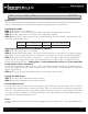
Alarm System www.firstechonline.com | www.compustar.com CM6300 Install Guide Option Programming Tables CM6300 Option Group 1 Optional Setting - Optional Setting - Optional Setting II III IV Feature Default Setting - I 1-02 Lock / Unlock pulse duration 0.8 sec 1-03 Driver's priority unlock Off On 1-04 Double pulse unlock Off 1-07 Unlock / Disarm With Trunk Release 1-08 1-09 2.5 sec 0.125 sec 3.
Alarm System www.firstechonline.com | www.compustar.
Alarm System www.firstechonline.com | www.compustar.
Alarm System CM6300 Install Guide www.firstechonline.com | www.compustar.com 1-04 Double Pulse Unlock - If enabled, this option will cause the system to double pulse the lock, unlock or both lock and unlock outputs. This can be used for vehicles that need two pulses to unlock or relock the doors. 1-07 Unlock / Disarm with Trunk Release - This option sets what the unlock and/or factory disarm wires do during remote trunk release.
Alarm System CM6300 Install Guide www.firstechonline.com | www.compustar.com 3-04 Starter-Kill – This option determines the mode of the anti-grind/starter-kill relay. Default 1: Anti-grind + starter-kill Option 2: Anti-grind only (no starter-kill) Option 3: Anti-grind + passive starter-kill: starter-kill activates in 45 seconds after ignition is turned off. 3-05 Anti-Jacking – This option requires the starter-kill relay to be wired to the ignition vs. the starter wire.
Alarm System CM6300 Install Guide www.firstechonline.com | www.compustar.com 3-15 Soft Disarm - When a vehicle has a factory alarm, and the Firstech alarm is triggered, you may have both alarms triggered at the same time. In the default setting, silencing the Firstech system will not send the disarm pulse to the factory system, therefore requiring the user to first silence the Firstech system and then unlock and disarm to silence the factory system.
Alarm System CM6300 Install Guide www.firstechonline.com | www.compustar.com 4-07 Aux 2 Input – This option changes the input behavior of the instant trigger wire on the Aux Input Sensor green connector. Default 1:. Will instant trigger with a negative (-) ground input. Option 2: Will pre-warn with a negative (-) ground input. Option 3: Will arm the alarm with a negative (-) ground input. Used when adding an alarm to a factory keyless entry system.
Alarm System CM6300 Install Guide Special Option Groups 1 & 2 www.firstechonline.com | www.compustar.com CM6300 IMPORTANT: The OP500 is required to change settings in Special Option Groups 1 and 2. Special Option Group 1 2 Aux 1 Output Timing – Option 4-01 must first be set to setting 4. This special option allows a specific output duration for Aux 1 to be programmed. 3 Aux 2 Output Timing – Option 4-02 must first be set to setting 4.
Alarm System www.firstechonline.com | www.compustar.com CM6300 Install Guide At the end of menu 4, if diesel mode or auxiliary setting functions were enabled – or if any of the auxiliary outputs were set to “Program”, the duration of these settings can now be adjusted. Following the auxiliary and diesel settings (if selected), the POC options will be displayed on the OP500. The POCs can be set between 0 (default) and 19. All are only available on the CM5000.
Alarm System www.firstechonline.com | www.compustar.com CM6300 Install Guide Lock + Unlock for 2.5 seconds then Lock + Unlock for 2.5 seconds Option Lock + Unlock for 2.5 Menu seconds then Lock + Key/ 2 Start for 2.5 seconds Option Menu 3 Lock + Key/Start for 2.5 seconds then Lock + Unlock for 2.5 seconds Option Lock + Key/Start for 2.5 Menu seconds then Lock + Key/ 4 Start for 2.5 seconds Hold Trunk + Key/ Start for 2.5 seconds Hold Trunk + Key/ Start for 2.5 seconds Hold Trunk + Key/ Start for 2.
Alarm System www.firstechonline.com | www.compustar.com CM6300 Install Guide Troubleshooting CM6300 Alarm LED Diagnostics When the alarm is triggered the LED on the RPS (if installed), Secure Valet (if installed) and the LED (if installed) will flash a certain amount of times as shown in the table below. This is intended for users with 1 Way remotes.
Alarm System CM6300 Install Guide www.firstechonline.com | www.compustar.com Whenever I try to arm the vehicle, it chirps the siren 3 times and will not arm. A: Check the hood and trunk trigger inputs. Do the door locks flip flop in polarity? A: No. You can use the CompuPack (relay pack) for high current positive (+) locks, or the DM600 harness used for low current 600mA positive (+) locks.
Alarm System CM6300 Install Guide Technical Support Contacts www.firstechonline.com | www.compustar.com CM6300 Firstech technical support is reserved for authorized dealers only. Monday - Friday: 888-820-3690 (8:00 am – 5:00 pm Pacific Coast Time) Email: support@compustar.com Web: www.compustar.com/dealersupport Wire Diagrams Click on the “Installogy Access Client” link found on your desktop.