
Manual Chapter 4

4-28 Setting Up and Using Laser Alignment Fixtures
Mounting a Sensor Head
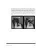
Note
Head A and B are identified with letters on the front panel.
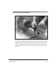
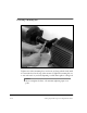
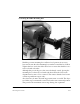
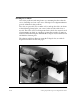
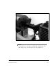
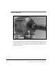
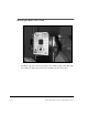
Place a sensor head on the two posts. It does not matter which side of the
coupling Head A or Head B is mounted on – the heads will be configured
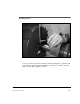
in the analyzer. Adjust to desired position and tighten each post clamp
finger tight. The vertical posts allow up to 1.5 inches (38 mm) of vertical
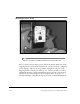
adjustment. If more vertical adjustment is needed, use the vertical exten-
sion blocks. See “Introduction to Special Applications” on page 4-46
through “Adding a 2-inch Block” on page 4-48 for additional information.