
User's Manual
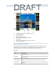
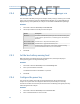
Table Of Contents
- Home
- Contents
- CSI 2140 Machinery Health Analyzer
- Introduction to the analyzer
- Transfer files with CSI 2140
- AMS Machinery Manager Data Transfer
- AMS Machinery Manager Standalone Data Transfer application
- Communication setup
- Routes and jobs
- Load a route from AMS Machinery Manager into the analyzer
- Load multiple routes from AMS Machinery Manager to the analyzer
- Load a Balance job from AMS Machinery Manager into the analyzer
- Dump a job from the analyzer to AMS Machinery Manager
- Dump a route from the analyzer to AMS Machinery Manager
- Dump a route or job from the analyzer to a folder on a computer
- Analyzer firmware and programs
- Screen captures
- Splash screens
- Printing
- Route
- Route overview
- Manage routes
- Set data collection and display parameters
- Set the plot type for collected data
- Enable or disable Point Advance to automatically move to the next measurement point
- Set High Frequency Detection averages
- Set the route data storage mode
- Set the overlap
- Set the plot type for live data
- Set the overall mode
- Set the integrate mode
- Enable or disable multi-channel group data collection
- Display a summary of data collected for grouped measurement points
- View or hide warning alarms on the Route Data Collection screen
- Restore default values for route data collection and display parameters
- Override the sensor setup for a route
- Enter new speed or load for a measurement point
- Tachometers
- Multiple inputs and measurements
- Collect route data
- Notes
- Plot data
- Run Analyze to collect data for a route measurement point
- View the measurement point setup and history
- Route reports
- Plots
- Analyze and Advanced Analyze
- Analyze overview
- Manage jobs
- Job Setup
- View all saved Analyze jobs
- Create an Analyze job
- Open a saved Analyze job
- Change the job ID
- Edit the equipment ID and description in a job
- Edit the measurement ID and description in a job
- Add a measurement
- Delete a measurement
- Delete data from the current measurement point
- Save a job to equipment in a route
- Set display parameters
- Multi-input measurements
- Sensors and inputs
- Tachometers
- Common data collection parameters
- Collecting data using an Analysis Expert
- Recommended uses of Analysis Experts
- Enable or disable the help text in the Analysis Experts
- High Frequency Analysis
- High Resolution Analysis
- Bearing/Gear Analysis - PeakVue
- Low Frequency Analysis - Slow Speed Technology
- Turning Speed Detection
- Laser Speed Detection
- Bump Tests
- Bump Test Equipment Off
- Bump Test Equipment Running
- Coast Down Peak Hold
- Coast Down Peak and Phase
- Rotor Bar Test Motor Current
- Order Tracking
- Synchronous Analysis
- Synchronous Analysis and Synchronous Averaging
- Orbit Plot
- Cross Channel Amplitude/Phase
- Collect data using Manual Analyze
- Listen to live vibration data in Analyze
- Redo a measurement
- Store data to a route or a job
- Review collected data
- Print an Analyze plot to AMS Machinery Manager
- Print a plot to a memory card
- Reset Analyze defaults
- Advanced Transient
- ODS/Modal
- ODS/Modal overview
- Manage jobs
- Sensors and inputs
- Tachometers
- Set up the plots
- Set up the job
- Collect ODS/Modal data
- Display the data for a measurement point
- Print an ODS/Modal plot to AMS Machinery Manager
- Print an ODS/Modal plot to a memory card
- Balance
- Balance overview
- Manage jobs
- Job Setup
- Sensor Setup
- Measurement Plane Setup
- Weight Plane Setup
- Acquire Data
- Balance correction
- Trim run
- One-run balance job
- Notes
- Balance summary reports
- Review balance data
- Manually enter balance job data
- Calculator Mode
- Determine another location to place weights
- Combine multiple weights on a rotor
- Calculate a new balance solution to use only the available weights
- Calculate weight placement using static and couple components
- Estimate trial weights
- Calculate weight location around the outside rotor circumference
- Calculate new balance solution to use only available locations and weights
- Amplification Factor
- Convert magnitude or frequency values to a different measurement unit
- Tips and additional information
- Balance accessories
- Technical specifications
- Glossary
- Index

Option Description
F4 Set Displace Set the displacement units. Not applicable for the Balance program.
The default is Peak to Peak.
F5 Set Non Standard Set the non-standard data types. Not applicable for the Balance
program. The default is RMS.
F6 Set Units Set to English Units, Metric Units, or SI Units. The default is English Units.
F8 Set dB Ref Configure acceleration, velocity, displacement, non-standard, and
microphone measurements displays for decibel reference. Enter a
value between 0.000000001 and 2. Not applicable for the Balance or
Route programs. The dB reference values are loaded with the route.
F10 Change Y Axis
Type
Set the amplitude axis type. Not applicable for the Balance program.
The default is Linear.
F11 Change X Axis
Type
Set the frequency axis type. Not applicable for the Balance program.
The default is Linear.
F12 Change Hz \ CPM Set the frequency to Hz Units (Hertz) or CPM Units (cycles per minute).
The default is Hz Units.
3. Press Enter.
2.10 Memory card
You can insert a memory card into the analyzer to store route or job files. You may want to
store some routes or jobs on specific cards to stay organized.
The memory card slot is located under the battery pack on the back of the analyzer. You
must remove the six screws to remove the battery pack and access the memory card slot.
You can use the File Utility to add, copy, move, or delete files from the inserted memory
card.
2.10.1 Insert or remove a memory card
WARNING!
• Insert or remove memory cards only when the analyzer is turned off.
• Remove the battery pack only in a non-hazardous area.
Procedure
1.
Ensure the power supply is disconnected from the analyzer.
2. Remove the battery pack from the back of the analyzer. See Section 2.5.6.
3. To insert a memory card, press the memory card, with the metal contacts facing up,
into the memory card slot until it clicks.
Introduction to the analyzer
24
DRAFT