
User's Manual
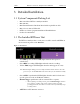
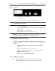
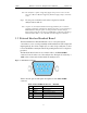
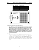
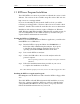
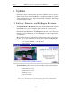
Table Of Contents
- Table of Contents
- 1. Overview
- 2. Quick Installation
- 3. Detailed Installation
- 4. Updates
- 5. Software Overview
- 6. Recording Wizard
- 7. Recording Options
- 8. Display Options
- 9. Reading a CATC Trace
- 10. Decoding Higher Protocols
- 10.1 Introduction
- 10.2 LMP and L2CAP Messages
- 10.3 Decoding and Viewing Higher Protocol Data
- 10.4 Tooltips
- 10.5 Viewing Packets in LMP and L2CAP Messages
- 10.6 Types of LMP and L2CAP Messages
- 10.7 Viewing L2CAP Channel Connections
- 10.8 Viewing Protocol Messages and Transactions
- 10.9 Changing Protocol Assignments
- 11. Other Features
- How to Contact CATC
- Warranty and License
- Index

14
BTTracer Protocol Analyzer User’s ManualCATC Version 1.0
Figure 2: Rear Panel
• Wide range AC connector module
— Power socket
— Enclosed 5x20 mm 2.0A 250 V fast acting glass fuse
Warning: For continued protection against fire, replace fuse only with the
type and rating specified above.
— Power on/off switch
• External Clock (EXT CLK) input for future enhancement (Note: THIS PORT
IS NOT USED)
• USB type “B” host computer connector
• Data In/Out DB-9 (9-pin) external interface connector
Warning: Do not open the BTTracer Analyzer enclosure. There are no
operator servicable parts inside. Refer servicing to CATC.
3.3 BTTracer System Setup
The BTTracer Analyzer is designed to work with either desktop or laptop
computers equipped with a functional USB interface. To set up the system
hardware,
• Attach the Antenna to the ANT connector. Set the antenna to
point up.
• Connect the Analyzer to an AC power source.
• Connect the External Interface Breakout Board to the Data
In/Out connector (optional).
• Connect to the analyzing PC via USB.
3.4 AC Power Source
Step 1 Connect the Analyzer box to a 100-volt to 240-volt, 50 Hz to
60 Hz, 100 W power outlet using the provided power cord.