
User's Manual
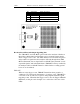
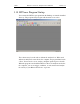
Table Of Contents
- Table of Contents
- 1. Overview
- 2. Quick Installation
- 3. Detailed Installation
- 4. Updates
- 5. Software Overview
- 6. Recording Wizard
- 7. Recording Options
- 8. Display Options
- 9. Reading a CATC Trace
- 10. Decoding Higher Protocols
- 10.1 Introduction
- 10.2 LMP and L2CAP Messages
- 10.3 Decoding and Viewing Higher Protocol Data
- 10.4 Tooltips
- 10.5 Viewing Packets in LMP and L2CAP Messages
- 10.6 Types of LMP and L2CAP Messages
- 10.7 Viewing L2CAP Channel Connections
- 10.8 Viewing Protocol Messages and Transactions
- 10.9 Changing Protocol Assignments
- 11. Other Features
- How to Contact CATC
- Warranty and License
- Index

15
BTTracer Protocol Analyzer User’s ManualCATC Version 1.0
Note The Analyzer is capable of supporting supply voltages between 100-volt and
240-volt, 50 Hz or 60 Hz, thus supporting all known supply voltages around the
world.
Step 2 Use the power switch located on the rear panel to turn the
analyzer unit on and off.
Note At power-on, the analyzer initializes itself in approximately ten seconds and
performs an exhaustive self-diagnostic that lasts about five seconds. The Trigger
LED illuminates during the power-on testing and turns off when testing is
finished. If the diagnostics fail, the trigger LED blinks continuously, indicating a
hardware failure. If this occurs, call CATC Customer Support for assistance.
3.5 External Interface Breakout Board
The External Interface Breakout Board is an accessory that allows
convenient access to several potentially useful standard fast TTL output and
input signals. It also offers a simple way to connect logic analyzers or other
tools to the BTTracer Analyzer unit. Four ground pins and one 5-volt pin are
provided.
The Breakout Board connects via a ribbon cable to the Data In/Out
connector located on the rear of the analyzer box. Each pin is isolated by a
100Ω series resistor and a buffer inside the Analyzer box.
Figure 3: Data In/Out Connector
Table 1 lists the pin-out and signal descriptions for the Data In/Out
connector.
Table 1: Data In/Out Connector – Pin-Out
Pin Signal Name Signal Description
1 +5V +5 Volts, 250mA DC source
2 TRG IN Trigger Input
3 GP IN General Purpose Input
4 TRG OUT Trigger Output
5 GP OUT General Purpose Output