
User's Manual
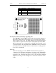
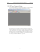
Table Of Contents
- Table of Contents
- 1. Overview
- 2. Quick Installation
- 3. Detailed Installation
- 4. Updates
- 5. Software Overview
- 6. Recording Wizard
- 7. Recording Options
- 8. Display Options
- 9. Reading a CATC Trace
- 10. Decoding Higher Protocols
- 10.1 Introduction
- 10.2 LMP and L2CAP Messages
- 10.3 Decoding and Viewing Higher Protocol Data
- 10.4 Tooltips
- 10.5 Viewing Packets in LMP and L2CAP Messages
- 10.6 Types of LMP and L2CAP Messages
- 10.7 Viewing L2CAP Channel Connections
- 10.8 Viewing Protocol Messages and Transactions
- 10.9 Changing Protocol Assignments
- 11. Other Features
- How to Contact CATC
- Warranty and License
- Index

16
BTTracer Protocol Analyzer User’s ManualCATC Version 1.0
Table 2: External Interface Breakout Board
Breakout Board External Output Signalling Pins
The "TRG OUT" and "G.P. OUT" pins found on the Analyzer’s Breakout
Board have similar functions. Both pins serve to transmit output signals
when a trigger event occurs. The main differences between the two pins is
in the number of signals that the Analyzer will send through them (TRG
OUT will transmit just one signal whereas G.P. OUT may transmit several
sequential signals), and in their initial state (TRG OUT is always enabled by
the Analyzer whereas G.P. OUT must be enabled in the recording options
before it can be utilized).
TRG OUT
When an event trigger occurs, TRG OUT transitions from ground to a
continuous 5 V signal on the first instance of a trigger event. TRG OUT is
a one-time event: it will not re-signal or change signals with subsequent
triggering events. When this first trigger event occurs, the Trigger LED will
illuminate (so this pin can be thought of as a reflection of the state of this
LED).
6 GND Ground
7 GND Ground
8 GND Ground
9 GND Ground
Pin Signal Name Signal Description