
User's Manual


CT-EM2506 ZigBee Ready RF Transceiver Modules
Computime Ltd. All rights reserved Confidential Page 12 of 16
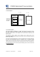
16. Antenna Design Considerations
The CT-EM2506 module includes an integrated PCB trace antenna. An optional MMCX
connector can be specified, enabling connection to a 50-ohm external antenna of the user’s
choice..
The PCB antenna employs an F-Antenna topology that is compact and supports an
omni-directional radiation pattern. To maximize antenna efficiency, an adequate ground
plane must be provided on the host PCB. If positioned correctly, the ground plane on the host
board under the module can contribute significantly to antenna performance.
The position of the module on the host board and overall design of the product enclosure
contribute to antenna performance. Poor design effects radiation patterns and can result in
reflection, diffraction, and/or scattering of the transmitted signal.
Here are some design guidelines to help ensure antenna performance:
• Never place the ground plane or route copper traces directly underneath the antenna
portion of the module.
• Never place the antenna close to metallic objects.
• In the overall design, ensure that wiring and other components are not placed near the
antenna.
• Do not place the antenna in a metallic or metallized plastic enclosure.
• Keep plastic enclosures 1cm or more from the antenna in any direction.
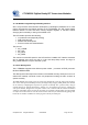
Test at 2440MHZ
__ Vertical Polarization Gain
(dBi)
Avg : -14.8
--- Horizontal Polarization Gain
(dBi)
Avg : -3.4