
Datasheet


TIC126 SERIES
SILICON CONTROLLED RECTIFIERS
1
APRIL 1971 - REVISED SEPTEMBER 2002
Specifications are subject to change without notice.
●
12 A Continuous On-State Current
●
100 A Surge-Current
●
Glass Passivated Wafer
●
400 V to 800 V Off-State Voltage
●
Max I
GT
of 20 mA
absolute maximum ratings over operating case temperature (unless otherwise noted)
NOTES: 1. These values apply for continuous dc operation with resistive load. Above 70°C derate linearly to zero at 110°C.
2. This value may be applied continuously under single phase 50 Hz half-sine-wave operation with resistive load. Above 70°C derate
linearly to zero at 110°C.
3. This value applies for one 50 Hz half-sine-wave when the device is operating at (or below) the rated value of peak reverse volta ge
and on-state current. Surge may be repeated after the device has returned to original thermal equilibrium.
4. This value applies for a maximum averaging time of 20 ms.
RATING SYMBOL VALUE UNIT
Repetitive peak off-state voltage
TIC126D
TIC126M
TIC126S
TIC126N
V
DRM
400
600
700
800
V
Repetitive peak reverse voltage
TIC126D
TIC126M
TIC126S
TIC126N
V
RRM
400
600
700
800
V
Continuous on-state current at (or below) 70°C case temperature (see Note 1) I
T(RMS)
12 A
Average on-state current (180° conduction angle) at (or below) 70°C case temperature
(see Note 2)
I
T(AV)
7.5 A
Surge on-state current at (or below) 25°C case temperature (see Note 3) I
TM
100 A
Peak positive gate current (pulse width ≤ 300 µs) I
GM
3 A
Peak gate power dissipation (pulse width ≤ 300 µs) P
GM
5 W
Average gate power dissipation (see Note 4) P
G(AV)
1 W
Operating case temperature range T
C
-40 to +110 °C
Storage temperature range T
stg
-40 to +125 °C
Lead temperature 1.6 mm from case for 10 seconds T
L
230 °C
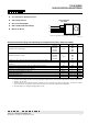
K
A
G
TO-220 PACKAGE
(TOP VIEW)
Pin 2 is in electrical contact with the mounting base.
MDC1ACA
1
2
3