
Product specifications


CRS-170A L-Band 1:1 Redundancy Switch Revision 3
Cables and Connections MN/CRS170A.IOM
4.3 Cabling to the CDM-570L
Examples for connecting a pair of CDM-570L modems together with the CRS-170A are provided in this
section. To enable 1:1 operation, refer to Chapter 3. MODEM AND SWITCH CONFIGURATION
in this manual and the CDM-570/570L Satellite Modem Installation and Operation Manual.
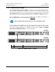
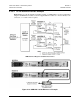
4.3.1 CRS-170 Æ CDM-570 1:1 Redundancy Kit KT/10860-1
The following table provides a reference as to how the items provided in Redundancy Kit
KT/10860-1 are utilized with all possible CDM-570L data interface configurations:
Kit KT/10860-1 CRS-170A Æ CDM-570L 1:1 Redundancy – Interface Cabling Reference
Qty/Kit
(REF)
Part No. Description Used For
Ch. 3
Fig
1 PL/10129-1 CRS-170A Switch – Top Assembly 1:1 Redundancy 3-13
4 CA/6357-4 RoHS-Compliant Cable – IF (Tx/Rx), 50Ω Type ‘N’, 4’
Modem Æ Switch IF Interface
3-13
2 CA/WR9378-4
Control Cable – Universal, DB-9M Æ DB-9M, 4’
Modem Æ Switch Control 3-13
1 CA/RB10461-1 Cable – 1:1 Y-Splitter, (2X) DB-25M Æ DB-25F RS-422/232 Interface 3-15
1 CA/WR10522-1 Cable – 1:1 Y-Splitter, (2X) DB-15M Æ DB-15F G.703 Balanced 3-16
1 KT/10553-1
G.703 Unbalanced Interface Kit containing:
(Qty 4) CA/BNC75OHM Cable – IF BNC, 1’
(Qty 2) CN/BNC-Tee-JPJ T-Adapter, 50Ω BNC
G.703 Unbalanced 3-17
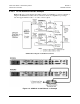
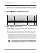
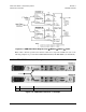
4.3.2 Basic Modem-to-Switch Connection
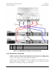
Figure 4-13 shows how to connect a pair of CDM-570L modems together with the CRS-170A
L-Band 1:1 Redundancy Switch module; the accompanying table lists the cable assemblies
provided in KT/10860-1 for this initial setup.
It is essential to ensure that the control and IF connections, both Rx and Tx, are made correctly. For
the available CDM-570L modem data interface configurations, refer to Sect. 4.3.3 in this chapter.
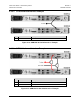
EXAMPLE: The Tx IF from ‘Modem A’ connects to the Tx IF port ‘Tx A’ on the CRS-
170A; similarly, the Tx IF from ‘Modem B’ connects to the Tx IF port ‘Tx B’ on the
CRS-170A.
The same logic applies for the Rx IF connections. Failure to observe this requirement will
result in system malfunction.
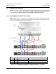
IMPORTANT
When connecting the Control cable between the CRS-170A and the modems,
ensure that screw locks on the ‘D’ type connectors are securely fastened.
This will prevent the accidental unmating of the cable, particularly when a
standby unit is being removed or replaced.
4–11