
Product specifications


CRS-170A L-Band 1:1 Redundancy Switch Revision 3
Cables and Connections MN/CRS170A.IOM
4.4 Cabling to the CDM-700
Examples for connecting a pair of CDM-700 modems together with the CRS-170A are provided in this
section. To enable 1:1 operation, refer to Chapter 3. MODEM AND SWITCH CONFIGURATION
in this manual and the CDM-700 Satellite Modem Installation and Operation Manual.
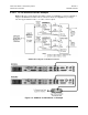
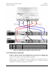
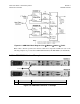
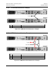
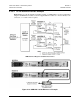
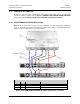
4.4.1 Basic Modem-to-Switch Connection
Figure 4-19 shows the basic connection for the CDM-700 to the CRS-170A Switch. All IF and
Control components are provided in the KT/12551 CRS-170A L-Band 1:1 Redundancy Kit (data
interface components/kits must be ordered separately):
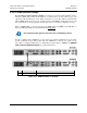
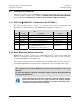
KT/12551 CRS-170A L-Band 1:1 Redundancy Kit
Item # QTY Part No. Description
1 1 PL/10129-1 CRS-170A Switch – Top Assembly
2 4 CA/6357-4 Cable – RoHS-Compliant, L-Band Type ‘N’, 4’
3 2 CA/WR12135-1 (Note 2) Cable Assy – RoHS-Compliant, Control Adapter
Figure 4-19. CDM-700 Basic Modem-to-Switch Connection – KT/12551
4–17