
Product specifications


CRS-170A L-Band 1:1 Redundancy Switch MN/CRS170A.IOM
Cables and Connections Revision 13
5–57
5.9 Cabling to the CDM-710
1)
For information on configuring the CRS-170A L-Band 1:1 Redundancy Switch
with the CDM-710GL High-Speed Satellite Modems for 1:1 operation, see:
• Chapter 4. MODEM
AND SWITCH CONFIGURATION
• CDM-710 Broadcast Satellite Modem Installation and Operation Manual
(CEFD P/N MN/CDM710.IOM)
2) For information on the cables and cable assemblies specified in this section, see
Appendix A. CABLE DRAWINGS.
5.9.1 CRS-170A CDM-710 Control and IF Interface Connections Using
Cabling Kit KT/12551
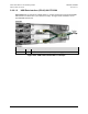
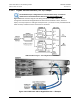
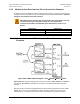
Terrestrial data interface components/kits must be ordered separately. See Sect.
5.9.2 for CDM-710 terrestrial data interface configuration and connection examples
and details.
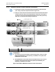
You must use Comtech EF Data’s KT/12551 1:1 Redundancy Control/IF Interface Cabling Kit
(Sect. 5.2.2) for your control and L-Band cabling connections. See Sect. 5.9.1.1 and Figure 5-46
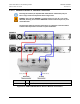
for details about the CDM-710 Modem-to-Switch Control Interface connections. See Sect.
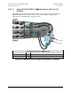
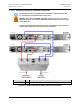
5.9.1.2 and Figure 5-47 for details about the CDM-710 Modem-to-Switch IF Interface
connections. The table included with each figure lists the items you will need from the KT/12551
kit for your initial setup.
CAUTION – It is ESSENTIAL that you make the control and the IF Rx and Tx
connections correctly
.