
Product specifications


CRS-170A L-Band 1:1 Redundancy Switch MN/CRS170A.IOM
Cables and Connections Revision 13
5–69
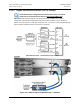
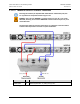
Figure 5-54 shows the block diagram typical for the kits shown in Sects. 5.10.2.1.1 through
5.10.2.1.3. For example, Sect. 5.10.2.1.1 identifies the interface kit used with the CDI-10 Dual
G.703 E3/T3/STS-1 and CDI-60 HSSI data interfaces.
With the exception of the CDI-70 Gigabit Ethernet data interface configuration shown in Sect.
5.10.2.2, which uses user-provided Ethernet cables and Layer 2 Switch, you must use one
interface kit per 1:1 modem pair for each interface (see examples for specific quantities).
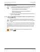
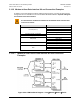
5.10.2.1.1 Dual G.703 E3/T3/STS-1 75Ω Data Interface (CDI-10) Kit
KT/12582 and HSSI Data Interface (CDI-60) Kit KT/12586
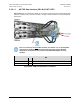
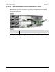
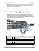
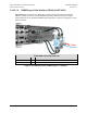
Figure 5-55 shows an example of a CDM-700 1:1 modem configuration with the CDI-10 Dual
G.703 Data Interface installed in Slot 1, and the CDI-60 HSSI Data Interface installed in Slot 2.
The figure depicts installation of one KT/12582 Dual G.703 Interface Kit (each kit can supply one
or two CDI-10 interfaces), and one KT/12586 HSSI Interface Kit.
KT/12582 G.703 (CDI-10) 75Ω Interface Kit
CEFD Part No.
Qty
Description
CA/BNC75OHM
8
Cable – IF BNC, 75
Ω
, 1’
RF/SA32KC-IN/OUT
4
Combiner – 2-way w/Bracket, 0.25-300 MHz, 75
Ω
BNC
KT/12586 HSSI (CDI-60) Interface Kit
CEFD Part No.
Qty
Description
PP/SC3523
1
Cable - RoHS-Compliant, HSSI ‘Y’ Splitter, (2X) HD-50M
HD-50F, 3”
Figure 5-55. CDM-700 CDI-10 G.703 E3/T3/STS-1, CDI-60 HSSI 1:1 Example
To/From User
To User
From User