
Product specifications

Ku-Band Satellite Transceiver Revision 9
Operation MN/KST2000AB.IOM
3–5
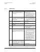
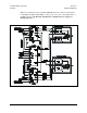
3.2 Initial Setup Redundant System
The following procedures are necessary to laboratory test a redundant KST-2000A/B system for
the first time. Refer to the “Communications with Redundant Systems” section in the “M&C
Software for Windows™” manual.
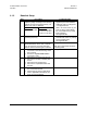
Step Procedure Remarks
1 Ensure that the system is set up , except the HPA
waveguide switch must be connected to a coupler ter-
mination or attenuator. and that the output of the
waveguide switches have not been attached to the
OMT.
2 Remove the PL/3003-1 cable connection between J2,
REMOTE, of the KST-2000A/B, unit B, and the
RJU-2000.
Unit A determination is made by the PL/8084-
1 cable P1 connection.
3 Apply AC power to KST-2000A/B, unit A.
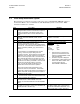
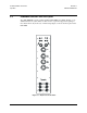
4 Using a KP-10, or a PC equipped with a terminal, or
Windows™ based M&C program, ensure
communication with unit A via the RJU-2000 Remote
connector J6. If communication is established use the
address command (<add/AS_x{cr}) to set unit A to
address 2.
If communication is not established begin trouble-
shooting. Ensure the proper cabling from the
computer to the RJU. Ensure that the communication
parameters of the computer match that of the KST-
2000A. Ensure the proper mode of communication is
being used (RS-485 or RS-422 see page 2-6 of this
manual). If necessary connect directly to KST unit A,
use RS-232 if the cabling is available. Use a terminal
emulator and poll the KST with the command
<*/AS_{cr}, this will globally poll the KST for it’s
address which is the most common problem.
Delete If the communication parameters for the
system are not known, the Windows based M&C
system has a utility that will search all combinations of
address, baud rate, and parity until communication is
established with the system.
KST-2000A Default Communication
Parameters:
Address 1
Baud Rate 9600
Parity Even
Stop bits 2
Data Length 7 bits
1. Using the KP-10 or terminal pro-
gram, send a miscellaneous com-
mand such as EQUIPMENT TYPE
(see Appendix B.8).
2. Confirm a response is displayed.
3. The Windows™ based status screen
will turn from RED to GRAY when
communications with the
KST-2000A/B is established.
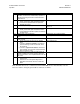
5 1. Repeat steps 2, 3 and 4 for Unit B.
2. Ensure that the remote serial address differs from
Unit A, typically set to address 3.
6 Reconnect the M&C cable between J4 of the
RJU-2000 and J2 of KST-2000A/B Unit A, and
between J5 of the RJU-2000 and J2 of KST-2000A/B
Unit B
7 Ensure that serial communications through the
RJU-2000, J6 connector, to each KST-2000A/B is still
possible (RS-485 or RS-422 only).
The Windows™ based status screen will turn
from RED to GRAY when communications
with the KST-2000A/B is established. Use
option/configuration to select redundancy.