
Product specifications

Ku-Band Satellite Transceiver Revision 9
Operation MN/KST2000AB.IOM
3–10
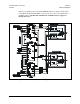
The RJU-2000 combines the individual REMOTE interface of each of the KST-2000A/B
systems into a common system M&C connector (J6). Because of the “Parallel” nature of
this interface, only EIA-485 (2 wire) and EIA-422 (4 wire), half duplex serial communi-
cations are supported. This connector provides a diode “OR’d” power supply to power a
KP-10, and routes unit A and B uplink and downlink fault relay outputs to the user. The
RJU-2000 performs status signal routing between KST-2000A/B unit A and B and switch
position command/indicators to each of the KST-2000A/B and TX RX and IF switches.
This is done through the 1:1 connector (J3) and TX (J1) and RX (J2) switch interfaces.
3.4 Connector Descriptions
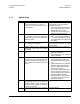
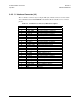
3.4.1 TX Switch Connector (J1)
The TX switch connector (J1), is a 6-pin, MS style male connector. It routes position
commands and indicators from the TX switch to each KST-2000A/B. Refer to
Table 3-1 for connector pinout.
Table 3-1. Connector J1 Pinout Description
Pin Description
A Switch position A command, 500 ms +28VDC pulse
B Switch command common
C Switch position B command, 500 ms +28VDC pulse
D Switch position A indicator (D and E connected position A)
E Switch position indicator common
F Switch position B indicator, (E and F connected position B)
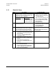
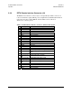
3.4.2 RX Switch Connector (J2)
The RX switch connector (J2) is a 6-pin, MS style male connector. It routes position
commands and indicators from the RX waveguide switch to each KST-2000A/B. Refer to
Table 3-2 for connector pinout.
Table 3-2. Connector J2 Pinout Description
Pin Description
A Switch position A command, 500 ms +28VDC pulse
B Switch command common
C Switch position B command, 500 ms +28VDC pulse
D Switch position A indicator (D and E connected position A)
E Switch position indicator common
F Switch position B indicator, (E and F connected position B)