
Product specifications

Ku-Band Satellite Transceiver Revision 9
Operation MN/KST2000AB.IOM
3–11
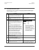
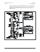
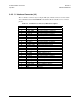
3.4.3 1:1 Interface Connector (J3)
The 1:1 interface connector (J3) is a 26-pin, MS style, female connector. It routes status
and commands between KST-2000A/Bs and switches. Refer to
Table 3-3 for connector
pinout.
Table 3-3. 1:1 Interface Connector J3 Pinout Description
Pin Signal Description
A TX_SW_CMD TX switch position A command
B RX_SW_CMD RX switch position A command
C IF_SW_CMD IF switch position A command
D A/B_UNIT GND, indicates unit A
E IF_IND_B IF switch position B indicator
F IF_IND_A IF switch position A indicator
G RX_IND_A RX switch position B indicator
H RX_IND_A RX switch position A indicator
J TX_IND_B TX switch position B indicator
K TX_IND_A TX switch position A indicator
L A_IND_COM Unit A indicator common
M A_CMD_COM Unit B command common
N GND Ground
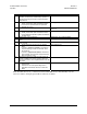
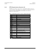
P TX_SW_CMD TX switch position B command
R RX_SW_CMD RX switch position B command
S IF_SW_CMD IF switch position A command
T A/B_UNIT GND, indicates unit A
U IF_IND_B IF switch position B indicator
V IF_IND_A IF switch position A indicator
W RX_IND_B RX switch position B indicator
X RX_IND_A RX switch position A indicator
Y TX_IND_B TX switch position B indicator
Z TX_IND_A TX switch position A indicator
a B_IND_COM Unit A indicator common
b B_CMD_COM Unit B command common
c GND Ground