
Product specifications


Ku-Band Satellite Transceiver Revision 9
Operation MN/KST2000AB.IOM
3–14
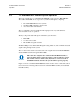
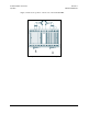
3.4.6 Interface M&C Connector (J6)
The interface M&C connector (J6) is a 26-pin, MS style, female connector. It provides
the system M&C interface with EIA-485 or EIA-422 control of the redundant
KST-2000A/B, provides diode OR’d +12V power for a KP-10, and routes uplink and
downlink fault relay contacts from each KST-2000A/B to the remote M&C system. Refer
to
Table 3-6 for connector pinout.
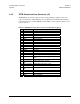
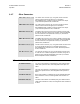
Table 3-6. Interface M&C Connector J6 Pinout Description
Pin Signal Description
A –TX/RX –RX –EIA-485 TX/RX or –EIA-422 RX
B –TX/RX –TX –EIA-485 TX/RX or –EIA-422 TX
C +TX/RX +RX +EIA-485 TX/RX or +EIA-422 RX
D +TX/RX +TX +EIA-485 TX/RX or +EIA-422 TX
E ULA_FLT_NC Uplink A fault relay, closed = fault
F ULA_FLT_CO
M
Uplink A fault relay common
G ULA_FLT_NO Uplink A fault relay, open = fault
H N/C No connection
J GND Ground
K N/C No connection
L GND Ground
M RESET Reset, (momentary low resets system)
N GND Ground
P N/C No connection
R GND Ground
S +12V +12VDC (KP-10 power supply output)
T 2/4 wire EIA-485 (open)/EIA-422 (ground) opera-
tion
U ULB_FLT_NC Uplink B fault relay, closed = fault
V ULB_FLT_CO
M
Uplink B fault relay, common
W ULB_FLT_NO Uplink B fault relay open = fault
X DLB_FLT_NC Downlink B fault relay, closed = fault
Y DLB_FLT_CO
M
Downlink B fault relay common
Z DLB_FLT_NO Downlink B fault relay, open = fault
a DLA_FLT_NC Downlink A fault relay, closed = fault
b DLA_FLT_CO
M
Downlink A fault relay common
c DLA_FLT_NO Downlink A fault relay, open = fault