
Product specifications


Ku-Band Satellite Transceiver Revision 9
Operation MN/KST2000AB.IOM
3–20
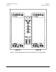
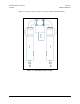
Each KST-2000A/B has built-in redundancy logic and the capability to control a TX, RX,
and IF switch. The 1:1 interconnect cable designates an A Unit and a B Unit. An A Unit
will become the primary interface for remote backup configuration commands. In addi-
tion, the A Unit will control the A position of the TX, RX, and IF switches; likewise the
B Unit controls the B position of the TX, RX, and IF switches.
The A Unit will pass operating mode and configuration information to the B Unit. The
B Unit will accept these commands through the 1:1 interface only. Fault information for
each unit is also passed to the other through this interface, so each KST-2000A/B is
aware of the fault status of the other. Uplink and downlink online assertions are made
through this interface also, thereby informing the other KST-2000A/B of which unit is
currently online. Whenever there is contention between the units, unit A always prevails.
This can happen when the A Unit uplink is online, and B Unit downlink is online, and
automatic dependent mode is enabled. In this mode, the entire up and down link of the
system must pass through a single KST-2000A/B; so, the A Unit will place its downlink
online.
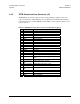
The user-selectable operating modes of the redundant KST-2000A/B are:
• Manual mode
• Automatic, independent switching
• Automatic, chain switch (dependent)
In order to enable any backup operating mode, a KP-10, or a PC running a terminal or
Windows ™ based M&C system is required. The user will not be able to enable backup
operation unless the RJU-2000 and two KST-2000A/B’s are connected via the 1:1 inter-
connect cable. The backup enable and backup mode of operation can only be selected
through the A Unit. Refer to Appendix B.6 for an explanation of these commands. Once
these commands are accepted by the A Unit, the B Unit will also assume this configura-
tion automatically.
The default setup after backup mode has been enabled will be manual mode and the up-
link and downlink switch position indicators will report the actual position of the TX and
RX switch.
In manual mode, the operator has full control over the uplink and downlink switch posi-
tions. They can be controlled through the Interface M&C (J6) with serial commands, or
manually by removing the weather-tight covers on the waveguide switches, and manually
rotating the switch. If the RX waveguide switch position is changed in this manner, the
RX IF switch will automatically change its position to match. This ensures that the entire
downlink selected is the one that is output by the system. If remote commands are issued
to place an uplink or downlink online, the command is issued to the KST-2000A/B unit
that will be assuming control.