
Product specifications


MBT-4000B Multi-Band Transceiver System Revision 1
External Connectors MN/MBT4000B.IOM
3–2
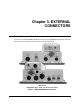
3.2 MBT-4000B External Connectors
Table 3-1 summarizes the external connections and identifies the chapter sections providing
connector pinout information.
Table 3-1. MBT-4000B External Connectors
Signal Side
(Sect.)
Module
Ref
Des
Name Sect. Function
IF
(3.2.1)
MBT-4000B
Base
Module
N/A
N/A
3.2.1.1
#10-32 Ground stud
J1
POWER
3.2.1.2
AC Power
J2 COMM 3.2.1.3
Serial communication and Summary
Fault
J3
UNIT 1 COMM
3.2.1.4
Communicate with BUC
J4
IF SWITCH
3.2.1.5
Monitor & Control IF Switch
J5
EXT REF
3.2.1.6
External 5 or 10 MHz Reference Input
J11
L-BAND OUT
UNIT 2
3.2.1.7 IF Output to Modem
BUC-4000
Module
J4
IF IN
3.2.1.8
IF Input from Modem
J6
COMM
3.2.1.9
Communicate with Base Module
RF
(3.2.2)
MBT-4000B
Base
Module
J7
REDUNDANT
LOOP
3.2.2.1
Connect for dual base redundant
operation
J12
L-BAND IN
3.2.2.2
L-Band Input from LNB
J9
AUX COMM
3.2.2.3
External Equipment Monitoring
J10
RF SWITCH
3.2.2.4
Monitor and Control RF Switch
BUC-4000
Module
J5 RF OUT 3.2.2.5 RF Output to SSPA