
Product specifications


MBT-4000B Multi-Band Transceiver System Revision 1
Appendix B MN/MBT4000B.IOM
B–5
the CLC=2 remote command). Acceptable percentage values are 20 to 50 in
increments of 1%. A value of 99 disables the alarm function.)
d. If a current is detected outside this window, an LNB current fault will be posted, but
the supply will not be disabled.
B.6 Gain Equalization of Redundant Units
Gain equalization in an MBT-4000B system is accomplished by issuing individual attenuation
settings to the specific BUCs.
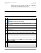
B.7 Redundancy Systems Check
Step Task
1
Set up two MBT-4000Bs with BUC modules installed in Slot 1.
The BUCs must match (e.g., C-Band → C-band).
2
Using a multi-drop EIA-485 connection, use the SPA=xxxx remote command to set the COMM address of the first
MBT to “1” (<“current address”/SPA=0001) and the COMM address of the other MBT to “2” (<“current
address”/SPA=0002).
3
With both MBTs connected to the multi-drop EIA-485 connection, use the RET? remote query on each base and BUC
module to verify communication and software versions.
4
Power down the system.
5
Connect the Redundant Loop Cable (CEFD P/N CA/WR11224-1) between the two MBT base unit “J7 |
REDUNDANCY LOOP” connectors..
6
Typical for each MBT base, connect an RF switch to the “J10 | RF Switch” connector. Note the “A” and “B” labels
on the ends of the Redundant Loop Cable – the MBT base connected to the “A” cable end will be connected to the
RF switch associated with the uplink (BUC/SSPA) path, and is referred to as “MBT1”. The MBT connected to the “B”
cable end will be connected to the RF switch associated with the downlink (LNB), and is referred to as “MBT2”.
7 Power up the system.
8 Enable two-unit redundancy by sending the RED=2 remote command to both MBT base units.
9
Place redundancy in AUTO mode by sending the RAM=xx remote command: RAM=11 to the MBT1 base, and
RAM=21 to the MBT2 base.
10 Verify that there are two solid LEDs on the “online” unit, and two flashing LEDs on the “offline” unit.
11
Unmute the BUCs by sending the MUT=0 remote command to both BUCs: <1A1/MUT=0 to BUC1, and <2A1/MUT=0
to BUC2. Then, unmute the Bias Tee by sending the MSP=0 remote command to both MBT bsee units: <1/MSP=0 to
MBT1, and <2/MSP=0 to MBT2.
12 Verify that there are two solid green LEDs on the “online” unit, and two flashing green LEDs on the “offline” unit.
13
Power down
MBT2
. This should force both switches to select
MBT1
.
14
Verify that both LEDs on MBT1 are
solid
green.
15 Power up MBT2.
16 Verify that both LEDs on MBT2 are flashing green.