
Product specifications


MBT-4000B Multi-Band Transceiver System Revision 1
Appendix B MN/MBT4000B.IOM
B–7
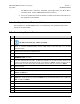
Step
Task
36
Connect the LNBs.
37 Enable the LNB voltage by sending the LCS=21 remote command to both MBT bases.
38
Verify the LNBs are drawing appropriate current by polling them with the RMS? remote query. Reported current for
LNB2 should be in the 200 to 400 mA range.
39
Calibrate the normal operating point of the LNB by sending the CLC=2 remote command to both MBT bases. This
records the operating current of the LNB and the MBT will monitor this current.
40
Set the desired current window (outside of which a fault will be declared) using the LCW=2xx remote command
(where xx=percentage of the nominal current allowed before a fault is declared – LCW=230 (30%) is a typical setting).
41
Disconnect the online LNB (indicated by the solid Unit 2 LED). The LED should now be flashing red and the LNB
switch should throw. The Unit 2 LED on the other MBT should stop flashing.
42
Restore the first LNB, and then fault the second. The same change in LEDs and switch position should be observed.