
Product specifications


Multi-Band Transceiver System Revision 0
Introduction MN/MBT4000B.IOM
1-5
1.3 SYSTEM OVERVIEW
The transceiver is constructed in a modular configuration. Common to the configuration
for any frequency band of operation is a base module, which provides the M&C, Power
Supply, and Reference function. A Band-specific BUC module is mounted to the base
module with clip-type fasteners. An internal bias tee provides a 10 MHz reference and
bias voltage for an external LNB.
1:1 MBT SUBSYSTEM
BUC 2 (Slot 1)
SSPA 2
1:1 MBT SUBSYSTEM
BUC 1 (Slot 1)
LOAD
L-BAND OUT
LOAD
L-BAND IN
SSPA 1
J3
J3
J10
J10
LOAD
TX
REJECT
FILTER
RX
REJECT
FILTER
J7
J7
J9
J9
AUX COMM 1
SWITCH 2 RF
SWITCH 1 RF
SWITCH 2 IF
REDUNDANCY
INTERLINK CABLE
AUX COMM 1
SWITCH 1 IF
L-BAND
MODEM
TX
RX
WAVEGUIDE
WAVEGUIDE
DUAL MBT-4000 REDUNDANT SWITCH
COMTECHEFDATA
MBT A MBT B
J5
J5
UNIT 1
COMM
UNIT 1
COMM
RF SWITCHES
SHOWN IN
POSITION
B
BIAST
BIAST
LNB2
LNB1
Note: 1:2 splitters/combiners may be substituted for the L-Band Input/Output switches.
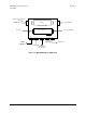
Figure 1-4. Typical, Chain Switched, Redundant Diagram