
Specifications

Options SDM-100A Satellite Modem
B–6 Rev. 0
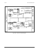
B.1.1.6 Loop Timing Operation
A loop timing option is provided. When loop timing is selected, the Doppler buffer
output clock is forced to the
RX clock by the M&C. An M&C-controlled MUX switches
the Send Timing (ST) pin to output the
RX clock. The RX clock is sent out the ST pin to
the appropriate interface drivers and on to the user. The user is left with the option of
clocking terrestrial data into the MUX on the transmit side with either the external clock
source Terminal Timing (TT) or the internal clock source. The internal clock source is
the same as the ST pin.
B.1.1.7 Baseband Loopback Operation
A baseband loopback option is provided. When selected, the input terrestrial data and
clock from the user are looped back to the user as the output terrestrial data and clock.
The terrestrial data and clock output from the DEMUX are also looped to the terrestrial
data and clock input at the MUX.
B.1.1.8 Non-ASYNC Operation
The ASYNC interface has pass-through capability. If ASYNC is turned off in the
CONFIG INTERFACE menu, then a standard RS-422 or V.35 interface is selected. The
modem will operate as a standard RS-422 or V.35 interface with no overhead. Instead of
changing jumpers on the interface PCB to change polarities for various signals, polarity
inversion is available in the UTILITY INTERFACE menu for the following signals:
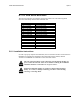
• Send Data (SD)
• Terminal Timing (TT)
• Request to Send (RS)
• Receive Data (RD)
• Receive Timing (RT)
• Receiver Ready (RR)
• Data Mode (DM)
• Monitor and Control (MC)
• Send Timing (ST)
B.1.1.9 ASYNC Channel RS-485 2- and 4-Wire
The ASYNC interface is compatible with either a 2- or 4-wire interface for the RS-485
channel. The 2- or 4-wire operation is selected in the UTILITY INTERFACE menu.
In the 2-wire mode, the RS-485 receivers are disabled whenever the data is to be
transmitted down the 2-wire interface. In the 4-wire mode, the receiver is always on.