
Product specifications


UT-4500-A Series Upconverters Revision 0
Appendix B MN-UT4500A
B–2
the faulted upconverter. The HSB interface is also used in the backup converter to monitor
configuration changes made to an online upconverter. Changes in frequency, gain, or polarity are
immediately entered into the backup table as well as information from new online units. The
high-speed bus does not interfere with the remote serial communication link access to any of the
upconverters in the chain.
B.2.2 Detachable Modules
Comtech EF Data's upconverters are designed with a detachable Input/Output Module (IOM)
which contains the signal path connectors. The IOM is utilized for single thread operation, or for
testing of the unit.
For redundant "Daisy Chain" operations, the online upconverters are provided with a detachable
Transmit Switch Module (TSM) replacing the IOM.
Refer to Chapter 3. REAR PANEL CONNECTORS, Sect. 3.2.2.2 for quick reference tables
for the modules available to both the UT-4500-A Series Upconverters and the DT-4500-A Series
Downconverters.
B.2.2.1 Upconverter Switching
Upconverter switching is implemented with a detachable TSM. The TSM contains IF and RF
transfer switches for input/output looping of the signal. Options for the TSM include Type ‘SMA’
connectors for the RF output signal, and 50 or 75" BNC connectors for the IF.
B.3 Redundant Configurations
Comtech EF Data UT-4500-A Series Upconverters can be configured in several different
redundant subsystem "Daisy Chain" configurations to meet the reliability requirements of a
communication system. These configurations include:
! 1:1 Redundant Systems
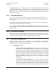
o Single Source IF Input Configuration: The online upconverter uses an IF & RF
transfer switch to switch the IF input and RF output signals. A single switched IF
input and RF output is provided to and from the online upconverter. The transfer
switches are contained in the TSM installed in the online upconverter. When a
fault occurs in the online upconverter, the TSM is de-activated to switch out the
online upconverter, and switch the IF input and RF output to the backup
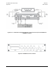
upconverter. Figure B-1 depicts the cable connections between the upconverters.
Figure B-2 shows the block diagram of this 1:1 redund
ant upconverter
configuration.
o Dual Source IF Input Configuration: Two IF inputs – IF Input #1 (priority)
and IF Input #2 – are switched in the TSM to provide redundant operation of the
upconverters. The upconverters provide two switched RF outputs – RF Output #1
(priority) and RF Output #2. If Upconverter #1 faults, Upconverter #2 backs up
the priority channel when IF Signal #2 and RF Signal #2 are not operational.