
Product specifications


UT-4500-A Series Upconverters Revision 0
Appendix B MN-UT4500A
B–3
Figure B-5 depicts the cable connections between the upconverters. Figure B-6
shows the block diagram of the 1:1 redundant, dual source RF input, upconverter
configuration.
! 1:N Redundant Systems
o IF and RF switches in the TSM are used to switch the IF input and RF output of a
faulted online upconverter to the backup upconverter. The IF input and RF output
to the redundant upconverter subsystem is connected to online upconverter #N.
Figure B-7 depicts the cab
le connections between the upconverters. Figure B-8
shows the block diagram for this 1:N redundant "Daisy Chain" upconverter
configuration.
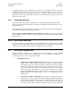
Figure B-1. 1:1 Redundant Configuration –Single Source IF Input with IOM-XX and TSM-XX
Installed
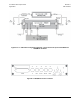
Figure B-2. 1:1 Redundant Configuration Diagram – Single Source RF Input with IOM-XX
and TSM-XX Installed