
Product specifications


UT-4500-A Series Upconverters Revision 0
Appendix B MN-UT4500A
B–8
B.4 Redundant System Configuration
B.4.1 Initial Configuration
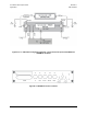
Redundant system configuration is controlled from the upconverter’s front panel configuration
menu. Each online unit is assigned a redundancy configuration address. This address is dependent
on the location of the online upconverter with reference to the backup. The unit closest to the
backup must be Upconverter # 1. The next unit down must be Upconverter # 2. Figure B-9
shows the appropriate entries for a 1:3 sy
stem.
R
EDUNDANCY-CONFIG?-ON---
-
CONVERTER-#-BU---1:03--
POWER ON
TRANSMIT
REMOTE
ON LINE
FAULT
STORED FAULT
STATUS
R
EDUNDANCY-CONFIG?-ON---
-
CONVERTER-#-01----POL-1
POWER ON
TRANSMIT
REMOTE
ON LINE
FAULT
STORED FAULT
STATUS
R
EDUNDANCY-CONFIG?-ON---
-
CONVERTER-#-02----POL-1
POWER ON
TRANSMIT
REMOTE
ON LINE
FAULT
STORED FAULT
STATUS
R
EDUNDANCY-CONFIG?-ON---
-
CONVERTER-#-03----POL-1
POWER ON
TRANSMIT
REMOTE
ON LINE
FAULT
STORED FAULT
STATUS
Figure B-9. Front Panel Displays
Configure the online units first, and then configure the backup unit. Redundant polling starts
when the backup is configured. If this polling starts before the online units are configured, a high-
speed bus fault will result. This fault should clear when configuration is completed. At this point,
control of the redundant system is performed from the backup upconverter.