
Product specifications

UT-4500A Series Upconverters Revision 0
Introduction MN-UT4500A
1–6
Changes in frequency, attenuation or polarity are entered into the backup table as they are made,
as well as information from new online units. The HSB does not interfere with the remote control
communications link for access to any of the converters in the "Daisy Chain".
1.3.2 RF Signal Conversion
As a typical example of the RF signal processing, in the Model UT-4514-A Upconverter, the 70
MHz IF input is mixed in the first mixer with a 1150 MHz IFLO signal. The IFLO is locked to a
5/10 MHz reference oscillator. The first mixer is located in the Signal Path Assembly.
The intermediate IF is 1220 MHz which is mixed in the second stage mixer with 12780 to 13280
MHz synthesizer signal to provide an RF output frequency of 14000 to 1451X MHz in 125 KHz
fine tuning steps. The synthesizer is also locked to the 5/10 MHz reference oscillator. The
second mixer is located in the upconverter Signal Path Module, and the synthesizer consists of the
Coarse/Fine Step Module and Sum Loop Module.
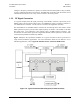
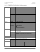
Figure 1-6 d
epicts the operational schematic for a typical UT-4500-A Series Upconverter in
single thread (standalone) applications. For more information about the UT-4500-A’s use in
redundant applications, refer to Appendix B. REDUNDANT SYSTEM OPERATION.
Figure 1-6. Typical Functional Block Diagram (UT-4512-A shown)