
Product specifications

UT-4500A Series Upconverters Revision 0
Introduction MN-UT4500A
1–7
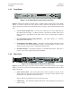
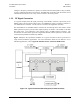
1.3.3 Monitor & Control
The Monitor & Control Assembly is designed to monitor the functions of the upconverter, and
provide the control for remote and local command inputs to the upconverter.
Remote control inputs are provided through the EIA-232C or EIA-485 communications port on
the rear of the panel, or by local operator inputs through the keypad on the front panel.
Local operator input commands and the status of the upconverter are displayed on the front panel
Vacuum Fluorescent Display (VFD) on the front panel.
A upconverter fault is indicated by the LED indicator on the front panel. Specific fault conditions
are displayed on the VFD through local keypad input commands.
1.3.4 Installation, Operation and Maintenance
Refer to Chapter 2. INSTALLATION for rack installation and mounting instructions.
Refer to Chapter 5. FRONT PANEL OPERATION for local operating instructions and
procedures.
Refer to Appendix A. REMOTE CONTROL for remote control operating instructions and
procedures.
Refer to Appendix B. REDUNDANT SYSTEM OPERATION for redundant system operating
instructions and procedures.
Refer to Appendix C. MAINTENANCE
AND TROUBLESHOOTING for maintenance and
troubleshooting procedures.