
Product specifications


5–1
Chapter 5. FRONT PANEL
OPERATION
5.1 Introduction
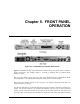
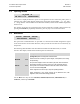
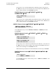
Figure 5-1. UT-4500-A Front and Rear Panel Views
Figure 5-1 identifies the key
operational features of the front and rear
panels of the UT-4500-A
Series Upconverter. This example depicts a UT-4505-A equipped with a Transmit Switch
Module, or TSM.
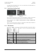
The front panel features (from left): Two Test Point Sample Ports, Six Light-Emitting Diode
(LED) Indicators, a Vacuum Fluorescent Display (VFD); and a six-button keypad.
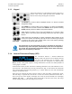
The Prime Power Switch, located on the rear panel, is an integral component of the IEC Line
Input (AC Power) Connector.
The function and behavior of the LED indicators, keypad, and VFD is described in detail in this
chapter. The keypad comprises six individual keyswitches. The user can use the keypad and
display to fully control and monitor the operation of the UT-4500-A from the front panel. The
user enters data via the keypad, and messages are displayed on the VFD. Nested menus display