
Product specifications

UT-4500-A Series Upconverters Revision 0
Front Panel Operation MN-UT4500A
5–2
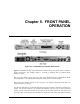
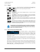
all available options and prompt the user to carry out a required action. The LEDs indicate, in a
summary fashion, the status of the unit.
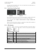
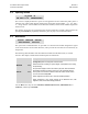
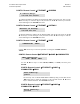
5.1.1 Switch Power On (Rear Panel)
UT-4500-A AC Power Switch UT-4500-A DC Power Switch
(Standard) (Optional)
Prior to turning on power to the unit, check to ensure that installation is complete, and verify that
the UT-4500-A is connected to the proper prime power source, RF Input, and IF Output.
For more information, refer to Chapter 2. INSTALLATION and Chapter 3. REAR PANEL
CONNECTORS.
Switch on the unit and verify the cooling fan is operational, the LED indicators illuminate as
expected, and the Vacuum Fluorescent Display is readable.
5.1.2 LED Indicators
The following table defines the operational condition,
when lit, of the six front panel LED indicators:
LED Color Operational Condition (When Lit)
POWER ON Green
Prime power is applied when the light is on.
OUTPUT ENABLE Yellow
Transmit function operating when the light is on.
REMOTE Yellow
In Remote Control Mode when the light is on.
ON LINE Yellow
Operating on-line to transmit data when the light is on.
FAULT Red
Fault condition exists when the light is on.
STORED FAULT Red
Faults stored and logged when the light is on.