
Product specifications


UT4500 Series Up Converter MN/UT4500.IOM
Maintenance and Troubleshooting Revision 2
86
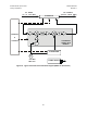
Power
Supply
Reference
Oscillator
Fine
Step
Module
Sum
Loop
Module
Monitor & Control Assembly
RF Converter
Prime Power Cord Input
5/10 MHz Ref. Osc. Input J2
P1
J1
J3
J4
J5
J7
J9
Summary Fault Relay Output
Serial Comm. Interface
(RS-485 / RS-232C)- COM 1
High Speed Bus (HSB)
IF Input (IF)
J6
J8
RF Loop Input (LP IN)
RF Loop Output (LP OUT)
RF Output (RF)
Transmit
I/O Switch
Module
(TSM)
IF Loop Input (LP IN)
IF Loop Output (LP OUT)
Figure 35. Converter Signal and Interconnecting Cable Diagram
(with TSM Switching Module).
7.2 MAINTENANCE TESTING
Use the instructions in Chapter 2, Installation, for installing the converter for checkout,
and the procedures in Chapter 3, System Operation, for operating the converter.
The converter is a Up Converter which translates the input IF frequency from 52 to 88
MHz (or optional 104 to 176 MHz) to an output RF frequency - for example, the RF
output frequency of the Model UT-4514 is 14000 to 14500 MHz. The IF input level is -
35 dBm (typical), and the RF output level is +10 dBm at 1 dB compression.
7.2.1 TEST POINT SAMPLES
The IF input and RF output can be monitored at the RF Sample Test Points on the front
panel. A BNC connector is provided for the IF sample, and an SMA connector is
provided for the RF output. The RF sample output level is -20 dBc nominal, and the IF
sample input level is -20 dBc nominal.