
Product specifications


UT4500 Series Up Converter MN/UT4500.IOM
Preface Revision 2
vii
Figures
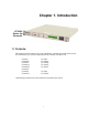
Figure 1. Front Panel (Model UT-4505 shown) ............................................................................ 2
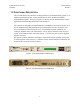
Figure 2. Rear Panel (shown with TSM Module).......................................................................... 2
Figure 3. Typical Functional Block Diagram (Model UT-4514 shown)....................................... 3
Figure 4. UT-4514 Dimensional Envelope.................................................................................. 14
Figure 5. Physical Configuration - Up Converter........................................................................ 15
Figure 6. Cable Interconnect Diagram......................................................................................... 23
Figure 7. Non-Redundant Converter Configuration .................................................................... 24
Figure 8. Non-Redundant Converter Configuration ................................................................... 24
Figure 9. Front Panel (Model UT-4505 shown) .......................................................................... 25
Figure 10. Rear Panel (with TSM Module and optional REF Output)........................................ 25
Figure 11. Keypad........................................................................................................................ 27
Figure 12. Converter Operating Command Functions................................................................. 28
Figure 13. Configuration Menu Commands - Redundancy OFF. ............................................... 29
Figure 14. Configuration Menu Commands - Redundancy ON, Backup Unit Not Selected ...... 30
Figure 15. Configuration Menu Commands - Redundancy ON and Backup Unit Selected ...... 31
Figure 16. Pre-Select Menu Commands ...................................................................................... 32
Figure 17. Monitor Status Menu Commands............................................................................... 32
Figure 18. Current Faults Menu Commands................................................................................ 33
Figure 19. Stored Faults Menu Commands ................................................................................. 33
Figure 20. Utility Function Menu Commands............................................................................. 34
Figure 21. 1:1 Redundant Configuration - Single Source IF Input.............................................. 44
Figure 22. 1:1 Redundant Configuration Diagram - Single Source ............................................ 44
Figure 23. 1:1 Redundant Configuration Diagram - Single Source RF Input ............................ 45
Figure 24. TSEQM Block Diagram............................................................................................. 45
Figure 25. 1:1 Redundant Configuration - Dual Source IF Input................................................ 46
Figure 26 1:1 Redundant Configuration Diagram Dual Source IF Input ................................. 46
Figure 27. 1:N Redundant Configuration with IOM-XX and TSM-XX Installed ...................... 47
Figure 28. 1:N Redundant Configuration Diagram with IOM-XX and TSM-XX Installed ...... 48
Figure 29. 1:3 Front Panel Displays ............................................................................................ 49
Figure 30. 1:3 System in AUTO Redundant Mode ..................................................................... 50
Figure 31. Converter #1 Being Backed Up.................................................................................. 51
Figure 32. Converter #1 in MANUAL, Others in AUTO............................................................ 52
Figure 33. Forced BU of Converter #1 ........................................................................................ 53
Figure 34. Typical Converter Functional Block Diagram (Model UT-4514 shown).................. 83
Figure 35. Converter Signal and Interconnecting Cable Diagram ............................................. 86