
Product specifications

UT4500 Series Up Converter MN/UT4500.IOM
Introduction Revision 2
10
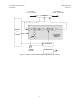
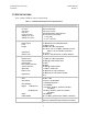
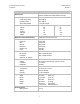
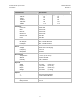
Table 4. UT-4514 and UT-4514/C/D/E/F Up Converter Specifications
Characteristic Specification
Frequency Range
UT-4514
UT-4514/C
UT-4514/D
UT-4514/E
UT-4514/F
Conversion
Step Size
Preset Channels
Stability Over Time
Stability Over Temp
14.00-14.50 GHz
12.75-13.25 GHz
13.75-14.50 GHz
14.70-15.00 GHz
12.75-14.50 GHz
Dual, No Inversion
125 KHz
32 Frequencies and Gains
± 1 x 10
-9
/Day
± 1 x 10
-8
0-50° C
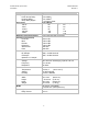
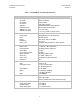
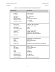
RF Output
Output Level
Intermodulation
Carrier Mute
Non–carrier Spurious
Carrier Spurious
AM to PM
Return Loss
Impedance
+10 dBm at 1 dB Compression
-38 dBc at 0 dBm Output
-70 dBc
-80 dBm
-65 dBc at 0 dBm Output
0.1°/dB at -5 dBm Out
20 dB Minimum with RF/IF Connector Module
18 dB Minimum with Switch Module
50 Ω
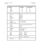
IF Input
Noise Figure
Level
Range
Impedance
Return Loss
13 dB Maximum at 0 dB Attenuation
-35 dB Typical
52 to 88 or 104 to 176 MHz, (optional 50 to 80
MHz or 100 to 180 MHz, see Note)
50 or 75 Ω
23 dB Minimum with RF/IF Connector Module or
Switch Module
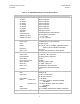
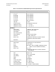
Transfer
Gain
Gain Adjust
Gain Stability
Ripple
Slope
Linear Group Delay
Parabolic Delay
Group Delay Ripple
External Reference
35 dB ± 2 dB
0-25 in 0.25 dB Steps
± 0.25 dB/Day
± 0.25 dB
0.05 dB/MHz
0.03 ns/MHz
0.01 ns/MHz 2
1 ns Peak-to-Peak
5 or 10 MHz, +3 dBm Nominal