
Product specifications


UT4500 Series Up Converter MN/UT4500.IOM
Installation Revision 2
23
Power
Supply
Reference
Oscillator
Fine
Step
Module
Sum
Loop
Module
Monitor & Control Assembly
Receive
I/O Switch
Module
RF Converter
Prime Power Cord Input
5/10 MHz Ref. Osc. Input J2
P1
J1
J3
J4
J6
J8
J5
J7
J9
Summary Fault Relay Output
Serial Comm. Interface
(EIA-485 / EIA-232C)- COM 1
High Speed Bus (HSB)
IF Output (IF)
IF Loop Input (LP IN)
IF Loop Output (LP OUT)
RF Input (RF)
(Not Used)
(Not Used)
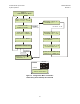
Figure 6. Cable Interconnect Diagram
2.4.5 CABLE CONNECTIONS FOR NON-REDUNDANT SYSTEM OPERATION
In non-redundant converter configuration the converter has an Input/Output Module
(IOM-XX) for the RF input and the IF Output. A converter with a Transmit Switch
Module may be operated in a non-redundant configuration if an IOM is unavailable.
Figure 7 is an illustration of the converter cable connections with an IOM installed.
Figure 8 is an illustration of the converter cable connections with a TSM installed.
2.4.6 CABLE CONNECTIONS FOR REDUNDANT SYSTEM OPERATION
In subsystems where a redundant converter configuration is used, the backup converter
has an Input/Output Module (IOM-XX) and the online converters have Transmit Switch
Modules (TSM-XX) which switch to the backup converter when a fault is detected.
Redundant system operation is discussed in Chapter 4, Redundant System Operation.