
Product specifications


25
Chapter 3. System Operation
3.1 OVERVIEW
This chapter contains instructions for operating the converter. Illustrations of the front
and rear panels are provided showing the keypad for operator input commands, LCD
Display, LED status indicators, and the connectors. Tables are provided to show the
control and operating functions of the converter.
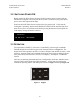
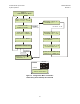
The front and rear panels are shown below. Table 12 lists of the operating functions for
the keypad, LCD display, LED indicators and test sample connections on the front panel.
Figure 9. Front Panel (Model UT-4505 shown)
Figure 10. Rear Panel (with TSM Module and optional REF Output)