
Product specifications


UT4500 Series Up Converter MN/UT4500.IOM
System Operation Revision 2
26
Table 12. Operating Functions – Front Panel
Item Reference Designation Functional Description
ENT
Enter key Enters commands into the converter.
CLR
Clear key Clears commands and data selected and not entered.
Right Arrow key Selects functions and the menu operating data.
Left Arrow key Selects functions and the menu operating data.
Up Arrow key Selects the operating menu and data values.
Down Arrow key Selects the operating menu and data values.
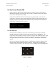
UT_4514-1
SW VER 4.06 SN45143513
LCD Display Displays commands and data entered
into the keypad.
Indicator Color Function
POWER ON
Green
Prime power is applied when the light is on.
TRANSMIT
Yellow
Transmit function operating when the light is on.
REMOTE
Yellow
In Remote Control Mode when the light is on.
ON LINE
Yellow
Operating on-line to transmit data when the light is on.
FAULT
Red
Fault condition exists when the light is on.
STORED FAULT
Red
Faults stored and logged when the light is on.
Item Reference
Designation
Function
RF SAMPLE RF An SMA connector test point to sample RF.
IF SAMPLE IF A BNC connector test point to sample IF.