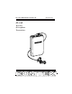
M-169 OPERATOR’S MANUAL (PRELIMINARY) M-169 Wireless Microphone Transmitter 357 West 2700 South • Salt Lake City, Utah 84115 • Phone: (800) 496-3463 • Fax: (801) 484-6906 • http://www.comtek.
TABLE OF CONTENTS Introduction ........................................................... 1 Setup ............................................................................... 2 Controls .................................................................. 3 Battery Removal/Replacement ...................................... 4 Battery Charging ...................................................... 5 Auxiliary Audio Input Operation ................................... 6-7 Snap-On Belt Clip .......
INTRODUCTION M-169 Wireless Microphone Transmitter T he M-169 transmitter offers the ultimate performance and versatility for applications where one-way personal communication is required. This compact, personal transmitter is ideal for instructors and presenters who must communicate with persons some distance away or in a noisy environment.
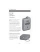
M-169 SETUP Setup a. Check to ensure that the M-169 transmitter’s radio frequency channel is the same as the associated COMTEK receiver’s channel. (Channels and mode of operation are indicated by the rotary channel selector switches on the back of the transmitter. See page 8 and 9.) b. Open the battery door cover on the transmitter (see page 4) and insert a new nine volt alkaline battery (Eveready E522 or equivalent). This type of battery will offer up to 20 hours of operation.
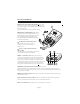
M-169 CONTROLS n CHANNEL AND MODE SWITCHES: These rotary switches are used to set the transmitter to the desired operating frequency and companded or non-companded mode of operation. (See page 8 and 9 for frequency selection chart.) o BATTERY COMPARTMENT: The battery compartment features a hinged battery cover and an alignment system that ensures proper battery polarity. Battery installation and removal is facilitated by simply manipulating the bottom of the battery.
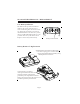
M-169 BATTERY REMOVAL / REPLACEMENT Low Battery Indicator The LED on the top of the transmitter indicates the status of the battery as well as indicating that the unit is turned on. When the transmitter is turned on, the LED illuminates. If the battery is low, the green LED will blink rapidly to warn you that the battery will soon be dead. Replace a low battery immediately. Battery indicator LED Battery Removal / Replacement Pull back battery door latch and allow battery cover door to spring open.
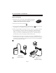
M-169 BATTERY CHARGING Battery Charging 1. Make sure that a seven cell 9 volt Ni-MH rechargeable battery is used with a minimum of 200 mAh capacity. (Alkaline batteries must not be charged.) TANT IMPOR 2. Make sure the M-169 is turned OFF. 3. Note that the red charging indicator on the charger is ON when the M-169 is plugged into the charger through the audio output jack. 4. When using the NBC 9-2C charger allow the battery to charge for 14 hours for a full charge. Unit must then be unplugged.
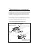
M-169 AUXILIARY AUDIO INPUT OPERATION Auxiliary Audio Input Operation The M-169 transmitter may transmit a variety of audio sources such as tape and C.D. players, TV and VCR’s, or any audio device having an auxiliary or line level audio output. The auxiliary input cable supplied with the M-169 transmitter (CB-36 ST) will operate with any device having a mini 3.5 mm jack, stereo or mono, and with line level or earphone level output.
M-169 AUX OPERATION (Cont.) / SNAP-ON BELT CLIP c. Turn on the transmitter with program from the audio source being fed to the transmitter. Observe the audio “voice” level modulation indicator. A full bright LED indicates full audio compression at 100% modulation. For best performance, the audio input gain should be adjusted for some low level LED luminescence during normal audio levels with occasional full bright peaks indicating 100% modulation. d.
M-169 FREQUENCY SELECTION Frequency Selection (169.445 - 171.905 MHz) The M-169 transmitter can operate on eight FCC dedicated assigned channels for wireless microphone operation under FCC Regulation Part 90. These channels may be used in two groups of four channels for multi-channel operation. (Refer to frequency charts on page 9.) After you have determined the channel on which you are going to operate, position the two rotary switches to indicate the channel and the mode of operation.
M-169 FREQUENCY INFORMATION 169 MHz BAND CHANNELS GROUP A CHANNEL FREQUENCY CHANNEL FREQUENCY 1 2 3 4 5 6 7 8 169.445 MHz 169.505 MHz 170.245 MHz 170.305 MHz 171.045 MHz 171.105 MHz 171.845 MHz 171.905 MHz 1 4 6 7 169.445 MHz 170.305 MHz 171.105 MHz 171.845 MHz GROUP B CHANNEL FREQUENCY 2 3 5 8 169.505 MHz 170.245 MHz 171.045 MHz 171.
M-169 OPTIONAL ACCESSORIES Optional Accessories 1. NBC 9-2C Battery charger 2. NBC 9-3-1 Digital fast charger 3. NBC 9-3-12 Digital 12-station fast charger 4. NH9-200 Rechargeable batteries 5. BC-216 Snap-on belt clip (supplied with M-175) 6. P1 Universal pouch 7. SM-185 Unidirectional electret condenser microphone 8. PSC-HM Headworn unidirectional electret microphone Auxiliary Audio Input Cords 9. CB-36 STM Stereo mini 3.5mm (supplied with M-175) 10. CB-36 RCA Phono plug (optional) 11.
M-169 SPECIFICATIONS Audio Input: • Microphone input impedance for electret type microphone - 3000 ohm • Aux/Line input impedance - 10 k ohm (0 dBV nominal) Connectors: Microphone - Micro-mini mono 2.5mm Auxiliary - TRS 3.5mm jack Audio: Tip and sleeve Battery Charging: Tip and sleeve Out-of-Band Emissions: Better than 50 dB below carrier R.F.
M-169 WARRANTY AND SERVICE Warranty COMTEK warrants this product to be free from defects in workmanship and material under normal use and conditions for a period of one year from date of original purchase. Items such as batteries, neckloops, and cords are not covered by the warranty. Damage due to misuse, ill treatment and unauthorized modification and repairs are not covered by this warranty.