
User's Manual


Page 3
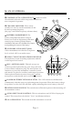
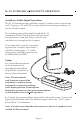
M-175 CONTROLS
n
COMPAND AUTO / OFF SWITCH: This switch overrides
the automatic selection of the companded channels to
non-companded operation.
o
CHANNEL SWITCHES: These rotary
switches are used to set the transmitter to the
desired operating frequency.
(See page 9 and 10 for frequency selection chart.)
p
BATTERY COMPARTMENT: The
battery compartment features a hinged
battery cover and an alignment system that
ensures proper battery polarity. Battery
installation and removal is facilitated by simply
manipulating the bottom of the battery.
q
AUXILIARY AUDIO INPUT JACK:
Allows transmitter to use line level, earphone
level, or fixed AUX as an audio source.
r
AUDIO “VOICE” MODULATION INDICATOR:
This indicator is used in making adjustment with the
Audio Input Gain Control.
s
MIC / ANTENNA JACK: This jack accepts an
electret type microphone having a 48” long cord with
a micro-mini 2.5mm mono plug. The microphone cord
functions as part of the transmitter’s antenna system
and must be in place for auxiliary audio input operation.
If microphone function is not necessary, the optional
microphone switch should not be on for this operation.
t
POWER / BATTERY STATUS INDICATOR: This LED indicator will illuminate
continuously when the unit is on, indicating normal operation. When the battery voltage
drops below 6 volts, the LED will flash rapidly, indicating that a new battery is needed.
u
OPTIONAL MIC SWITCH: This switch turns off the microphone without turning off
the transmitter carrier.
v
AUDIO INPUT GAIN CONTROL: This is a microphone and AUX level input gain
control. This control is used with the “Voice” modulation indicator.
w
ON / OFF SWITCH: This switch turns the transmitter on and off.