BST-25 / TV 5-6 OPERATOR’S MANUAL (76-88 MHz) Synthesized Base Station Transmitter 357 West 2700 South • Salt Lake City, Utah 84115 • Phone: (800) 496-3463 • Fax: (801) 484-6906 • www.comtek.
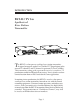
INTRODUCTION BST-25 / TV 5-6 Synthesized Base Station Transmitter T he BST-25 is a low power auxiliary base station transmitter designed to operate under Part 74 of the FCC Regulations in the unused TV channel 5 and TV channel 6 spectrum (76.2 to 87.8 MHz). This transmitter, along with a personal receiver, is used in a TV production studio for IFB and talent cueing. It may also be used on remote location from an ENG truck for the same application.
OPERATING INSTRUCTIONS Equipment Placement If the BST-25 base station is to be rack mounted, a remote antenna must be used. The base station should be mounted away from equipment that uses large power transformers to reduce 60 Hz hum possibilities. If the base station is to be used outside of a traditional rackmounted environment, the screw-in whip antenna should be free of any metallic objects when fully extended.
Power Requirements The BST-25 base station is designed to be powered by 12 volts DC. A power adaptor is furnished for use with standard 110V AC. The on/off switch on the front panel of the base station turns on the transmitter. Audio Input Connections The base station transmitter has facilities for audio input from a mic, line, or speaker level source. The mic/line level audio input is a transformer balanced input and requires a standard XLR-3 male connector.
OPERATING INSTRUCTIONS (continued) d. Plug the adaptor into a standard AC outlet and plug the power connector into the DC input jack of the transmitter. Turn the display switch on the front of the transmitter "ON" to allow monitoring of the transmitter frequency. Turn the main power switch on the front of the base station to the "ON" position. The front display should now be illuminated. e.
Audio Adjustments In order to ensure the highest possible transmission fidelity, the transmitter must be modulating at least 50% with normal speech (-3 dB on the VU meter). This adjustment is made in the following manner: a. Ensure that the audio source has been optimized for best signal-to-noise ratio. b. The “MIC/LINE” switch located at the back of the transmitter should be switched to the appropriate setting: "MIC" for mic level or weak line level input; “LINE” level for line level input. c.
OPERATING INSTRUCTIONS (continued) If you are using this transmitter in a area which does not have a TV station operating on channel 5, you can use one of the channels in the TV 5 range. Conversely, if the area does not have a station on TV 6, you can operate on one of the TV 6 channels. Note: It is unlawful to operate this transmitter in a band that is already occupied by a TV station.
Speech EQ On the back of the transmitter there is a switch labeled “EQ”. With this function enabled (switch up), the audio dynamics and frequency response are processed to improve intelligibility of speech. If the primary audio source is going to be speech, you should enable this processing! If the main audio source is going to include music information, you should disable it. You may want to experiment to determine which position sounds most pleasing with the program source you intend to use.
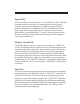
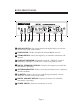
BST-25 FRONT PANEL 1 2 3 4 5 6 7 8 9 1 DISPLAY SWITCH: This switch disables the digital display to conserve current when used with a battery. 2 TONE SWITCH: Enables/disables the internal 400 Hz test tone. 3 TUNING SWITCH: Selects the frequency on which the transmitter will operate. 4 LOCK OUT INDICATOR: Illuminates when the “TUNING” switch is disabled by setting the “LOCK OUT” switch (rear panel) to “ON”.
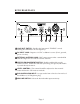
BST-25 REAR PANEL 10 11 12 13 14 15 16 10 LOCK OUT SWITCH: Disables the front panel “TUNING” switch, locking the transmitter on one frequency. 11 DC INPUT JACK: Requires 12 VDC at 500 mA source (Pin-1 ground, pin-4 +12 volts). 12 EXTERNAL ANTENNA JACK: BNC connector provides a standard 50 ohm RF output for use with an external antenna. 13 SPEECH ENHANCEMENT SWITCH: Enables and disables speech enhance feature. Enable this function (switch up) for speech, and disable it (switch down) for music.
BST-25 TV CHANNEL 5 FREQUENCY CHART CHANNEL FREQUENCY CHANNEL FREQUENCY 5-1 76.200 MHz 5-31 79.200 MHz 5-2 76.300 MHz 5-32 79.300 MHz 5-3 76.400 MHz 5-33 79.400 MHz 5-4 76.500 MHz 5-34 79.500 MHz 5-5 76.600 MHz 5-35 79.600 MHz 5-6 76.700 MHz 5-36 79.700 MHz 5-7 76.800 MHz 5-37 79.800 MHz 5-8 76.900 MHz 5-38 79.900 MHz 5-9 77.000 MHz 5-39 80.000 MHz 5-10 77.100 MHz 5-40 80.100 MHz 5-11 77.200 MHz 5-41 80.200 MHz 5-12 77.300 MHz 5-42 80.300 MHz 5-13 77.
BST-25 TV CHANNEL 6 FREQUENCY CHART CHANNEL FREQUENCY CHANNEL FREQUENCY 6-0 82.100 MHz 6-30 85.100 MHz 6-1 82.200 MHz 6-31 85.200 MHz 6-2 82.300 MHz 6-32 85.300 MHz 6-3 82.400 MHz 6-33 85.400 MHz 6-4 82.500 MHz 6-34 85.500 MHz 6-5 82.600 MHz 6-35 85.600 MHz 6-6 82.700 MHz 6-36 85.700 MHz 6-7 82.800 MHz 6-37 85.800 MHz 6-8 82.900 MHz 6-38 85.900 MHz 6-9 83.000 MHz 6-39 86.000 MHz 6-10 83.100 MHz 6-40 86.100 MHz 6-11 83.200 MHz 6-41 86.200 MHz 6-12 83.
BST-25 BST-25 TV CHANNEL 5 FREQUENCY GROUPS TV CHANNEL 6 FREQUENCY GROUPS GROUP ONE GROUP ONE CHANNEL FREQUENCY CHANNEL FREQUENCY 5-3 5-6 5-10 5-15 5-21 5-34 5-42 5-56 76.400 MHz 76.700 MHz 77.100 MHz 77.600 MHz 78.200 MHz 79.500 MHz 80.300 MHz 81.700 MHz 6-4 6-7 6-9 6-13 6-20 6-30 6-38 6-50 82.500 MHz 82.800 MHz 83.000 MHz 83.400 MHz 84.100 MHz 85.100 MHz 85.900 MHz 87.100 MHz GROUP TWO GROUP TWO CHANNEL FREQUENCY CHANNEL FREQUENCY 5-5 5-7 5-13 5-33 5-38 5-47 5-54 5-57 76.600 MHz 76.
BST-25 INTERNAL ADJUSTMENTS NOTE: The COMPAND switch must be set to the OFF position for use with “Walkman” FM band type receivers and TV monitors. Must be set to the ON position for use with PR-25 and PR-216/TV 5-6 receivers.
BST-25 ACCESSORIES Included Accessories 1. C-16 Carrying case 2. BST-25 Operator’s manual 3. TWA-72 Whip antenna 4. BST-25 Base station transmitter 5.
BST-25 ACCESSORIES Optional Accessories 1. RDA-2 Remote dipole antenna 2. PRA-5/6 Phase-Right antenna 3. MO-1/4 wave vehicle installation antenna or MO-1/4 wave magnetic mount antenna 4. PRA-B Phase-Right wall mounting bracket 5. RMK 25 Single rack-mount face plate 6.
BST-25 / TV 5-6 SPECIFICATIONS Audio Inputs: • Mic XLR, 600 ohm balanced -40 dBV (nominal) • Line XLR, 10 k ohm balanced 0 dBV (nominal) Connectors: • XLR-3 Female audio input connector for mic and line input • XLR-4 Male power input 12 volts • BNC type RF output connector Operation Indicators: • LED Bargraph VU Meter displays audio input (modulation) • Two-Digit Alpha Numeric Display shows operating channel • Five-Digit Numeric Display shows operating frequency • Antenna Indicator displays deficient anten
WARRANTY AND SERVICE Warranty COMTEK transmitters and receivers are warranted to be free from defects in workmanship and material under normal stand-alone use and conditions for a period of two years from date of original purchase. Items such as headphones, earphones, neckloops, and cords are warranted to be free from defects in workmanship and material for a period of 90 days from the date of original purchase. Batteries are not covered by this warranty.