CT-5361 Wireless ADSL2+ Router User’s Manual Version A2.
Warning Before servicing or disassembling this equipment, always disconnect all power and telephone lines from the device. Use an appropriate power supply and a UL Listed telephone line cord. Specification of the power supply is clearly stated in Appendix C Specifications. Preface This manual provides information to network administrators. It covers the installation, operation and applications of the ADSL router.
Copyright Copyright© 2007 Comtrend Corporation. All rights reserved. The information and messages contained herein are proprietary to Comtrend Corporation. No part of this document may be translated, transcribed, reproduced, in any form, or by any means without prior written permission by Comtrend Corporation. Technical support When you find the product out of service, or that it doesn’t work properly, please contact technical support engineer for immediate servicing or email to INT-support@comtrend.
Table of Contents CHAPTER 1 INTRODUCTION ......................................................................................................6 1.1 FEATURES ..................................................................................................................................6 1.2 APPLICATION .............................................................................................................................7 1.3 FRONT PANEL LED INDICATORS..........................................
6.3.2 Port Triggering ...............................................................................................................49 6.3.3 DMZ Host .......................................................................................................................51 6.3.4 ALG ................................................................................................................................52 6.4 SECURITY ..............................................................................
9.7 SAVE AND REBOOT ..................................................................................................................97 APPENDIX A: FIREWALL ................................................................................................................98 APPENDIX B: PIN ASSIGNMENTS...............................................................................................104 APPENDIX C: SPECIFICATIONS.....................................................................................
Chapter 1 Introduction The CT-5361 is an 802.11g (54Mbps) wireless and wired Local Area Network (WLAN) ADSL router. Four 10/100 Base-T Ethernet ports provide wired LAN connectivity with an integrated 802.11g WiFi WLAN Access Point (AP) for wireless connectivity. The CT-5361 ADSL router provides state of the art security features such as WPA data encryption Firewall, VPN pass through.
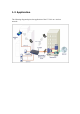
1.2 Application The following diagram depicts the application of the CT-5361 on a wireless network.
1.3 Front Panel LED Indicators The front panel LEDs are shown in the picture below, followed by an explanation in the table below. LED Color Mode Function POWER Green On The router is powered up. Off The router is powered down. On An Ethernet Link is established. Off An Ethernet Link is not established. Green Blink Data transmitting or receiving over LAN. Green On The wireless module is ready and idle. Off The wireless module is not installed.
Chapter 2 Installation 2.1 Hardware Installation In the rear panel, there is a reset button. To load the factory default settings, hold the reset button down for at least 5 seconds. Reset button Power button Follow the instructions below to complete the hardware connections. Connection to LINE port If you wish to connect both the router and a telephone, connect the LINE port to a POTS splitter with a RJ11 connection cable. Connection to LAN port To connect to a hub or PC, use a RJ45 cable.
Caution 1: If the router fails to power up, or it malfunctions, first verify that the power supply is connected correctly. Then power it on again. If the problem persists, contact our technical support engineers. Caution 2: Before servicing or disassembling this equipment always disconnect all power cords and telephone lines from the wall outlet.
Chapter 3 Login via the Web Browser This section describes how to manage the router via a Web browser via the remote end. You can use a web browser such as Microsoft Internet Explorer, or Netscape Navigator. (The Web page is best viewed with Microsoft Internet Explorer 5.0 and later): A unique default user account is assigned with user name root and password 12345. The user can change the default password later when logged in to the device. 3.
3.2 Login Procedure Perform the following steps to bring up the Web user interface and configure the CT-5361. To log on to the system from the Web browser, follow the steps below: STEP 1: Start your Internet browser. Type the IP address for the router in the Web address field. For example, if the IP address is 192.168.1.1, type http://192.168.1.1 STEP 2: You will be prompted to enter your user name and password. Type root in the user name and 12345 in the password field, and click OK.
3.3 Default Settings During power on initialization, the CT-5361 initializes all configuration attributes to default values. It will then read the configuration profile from the Permanent Storage section on the flash memory. The default attributes are overridden when identical attributes with different values are configured. The configuration profile in Permanent Storage can be created via the Web user interface or telnet user interface, or other management protocols.
Chapter 4 Quick Setup After login, the Quick Setup screen appears as shown. Note: The selections available on the left side of menu are based upon the configured connection. Shown here is the Device Info screen for your reference.
4.1 WAN Click Device Info on the menu bar to display the WAN option. Then, click WAN on the Device Info menu bar to display the configured PVC(s) and the status. VPI/VCI Shows the values of the ATM VPI/VCI Con. ID Shows the connection ID Category Shows the ATM service classes Service Shows the name for WAN connection Interface Shows connection interfaces Protocol Shows the connection type, such as PPPoE, PPPoA, etc.
4.2 Statistics Selection of the Statistics screen provides statistics for the Network Interface of LAN, WAN, ATM and ADSL. All statistics screens are updated every 15 seconds.
4.2.1 LAN Statistics The Network Statistics screen shows interface statistics for ATM AAL5 interface, Ethernet and USB interfaces. (The Network Statistics screen shows the interface statistics for the LAN interface. Here provides byte transfer, packet transfer, Error and Drop statistics for the LAN interface.
4.2.2 WAN Statistics Service Shows the service type VPI/VCI Shows the values of the ATM VPI/VCI Protocol Shows the connection type, such as PPPoE, PPPoA, etc.
4.2.3 ATM statistics The following figure shows the ATM statistics screen. ATM Interface Statistics Field Description In Octets Number of received octets over the interface Out Octets Number of transmitted octets over the interface In Errors Number of cells dropped due to uncorrectable HEC errors In Unknown Number of received cells discarded during cell header validation, including cells with unrecognized VPI/VCI values, and cells with invalid cell header patterns.
ATM AAL5 Layer Statistics over ADSL interface Field Description In Octets Number of received AAL5/AAL0 CPCS PDU octets Out Octets Number of received AAL5/AAL0 CPCS PDUs octets transmitted In Ucst Pkts Number of received AAL5/AAL0 CPCS PDUs passed to a higher-layer for transmission Out Ucast Pkts Number of received AAL5/AAL0 CPCS PDUs received from a higher layer for transmission In Errors Number of received AAL5/AAL0 CPCS PDUs received in error. The types of errors counted include CRC-32 errors.
4.2.4 ADSL Statistics The following figure shows the ADSL Network Statistics screen. Within the ADSL Statistics window, a bit Error Rate Test can be started using the ADSL BER Test button. The Reset button resets the statistics.
Field Mode Description Line Coding format, that can be selected G.dmt, G.lite, T1.413, ADSL2 Type Channel type Interleave or Fast Line Coding Trellis On/Off Status Lists the status of the DSL link Link Power State Link output power state. SNR Margin (dB) Signal to Noise Ratio (SNR) margin Attenuation (dB) Estimate of average loop attenuation in the downstream direction. Output Power (dBm) Total upstream output power Attainable Rate (Kbps) The sync rate you would obtain.
4.2.5 Route Choose Route to display the routes that the route information has learned. 4.2.6 ARP Click ARP to display the ARP information.
4.2.7 DHCP Click DHCP to display the DHCP information.
Chapter 5 Quick Setup The Quick Setup allows the user to configure the ADSL router for DSL connectivity and Internet access. It also guides the user though the WAN network setup first and then the LAN interface setup. You can either manually customize the router or follow the online instruction to set up the router. The CT-5361 ADSL router supports the following five network operating modes over an ATM PVC WAN interface.
Note: Up to eight PVC profiles can be configured and saved on the flash memory. To activate a particular PVC profile, you need to navigate all the Quick Setup pages until the last summary page, then click on the Finish button and reboot the system. 5.1 Auto Quick Setup The auto quick setup requires the ADSL link to be up. automatically detect the PVC. The ADSL router will You only need to follow the online instructions that you are prompted. 1. Select Quick Setup to display the DSL Quick Setup screen.
5.2 Manual Quick Setup STEP 1: Click Quick Setup and un-tick the DSL Auto-connect checkbox to enable manual configuration of the connection type. Un-tick this checkbox to enable manual setup and display the following screen. STEP 2: Enter the Virtual Path Identifier (VPI) and Virtual Channel Identifier (VCI). Select Enable Quality Of Service if required. Click Next.
STEP 3: STEP 3: Then, choose the Encapsulation mode. Select Enable 802.1q (by ticking the box) if required, and input a number for the VLAN ID. Click Next. STEP 4: Click Next to display the following screen. Choosing different connection types pops up different settings requests. Enter appropriate settings that are requested by your service provider. The following descriptions state each connection type setup separately.
5.2.1 PPP over ATM (PPPoA) and PPP over Ethernet (PPPoE) 1. Select the PPP over ATM (PPPoA) or PPP over Ethernet (PPPoE) radio button and click Next. The following screen appears: PPP USERNAME/PPP PASSWORD/ PPPOE SERVICE NAME: The PPP Username, PPP password and the PPPoE Service Name entries are dependent on the particular requirements of the ISP or the ADSL service provider. The WEB user interface allows a maximum of 256 characters in the PPP user name and a maximum of 32 characters in PPP password.
Disconnect if no activity The CT-5361 can be configured to disconnect if there is no activity for a period of time by selecting the Dial on demand check box. When the checkbox is ticked, you need to enter the inactivity timeout period. The timeout period ranges from 1 minute to 4320 minutes. PPP IP Extension The PPP IP Extension is a special feature deployed by some service providers. Unless your service provider specially requires this setup, do not select it.
Use Static IP Address Unless your service provider specially requires this setup, do not select it. If selected, enter your static IP address. Enable IGMP Multicast checkbox: Tick the checkbox to enable IGMP multicast (proxy). IGMP (Internet Group Membership Protocol) is a protocol used by IP hosts to report their multicast group memberships to any immediately neighboring multicast routers. MTU This option allows us to change the MTU size for WAN interface, PPPoE and PPPoA.
3. After entering your settings, select Next. The following screen appears. This page allows the user to configure the LAN interface IP address, subnet mask and DHCP server. If the user would like this ADSL router to assign dynamic IP address, DNS server and default gateways to other LAN devices, select the button Enable DHCP server on the LAN to enter the starting IP address and end IP address and DHCP leased time. 4. The following screen will be displayed.
5. Click Next to display the WAN Setup-Summary screen that presents the entire configuration summary. Click Save/Reboot if the settings are correct. Click Back if you wish to modify the settings. 6. After clicking Save/Reboot, the router will save the configuration to the flash memory, and reboot. again. The Web UI will not respond until the system is brought up After the system is up, the Web UI will refresh to the Device Info page automatically.
5.2.2 MAC Encapsulation Routing (MER) To configure MER, do the following. 1. Select Quick Setup and click Next. 2. Enter the PVC Index provided by the ISP and click Next. 3. Select the MAC Encapsulation Routing (MER) radio button, and click Next. The following screen appears. Enter information provided to you by your ISP to configure the WAN IP settings. Notice: DHCP can be enabled for PVC in MER mode if Obtain an IP address automatically is chosen.
4. Click Next to display the following screen. Enable NAT checkbox: If the LAN is configured with a private IP address, the user should select this checkbox. The NAT submenu on the left side main panel will be displayed after reboot. The user can then configure NAT-related features after the system comes up. If a private IP address is not used on the LAN side, this checkbox should be de-selected to free up system resources for better performance.
5. Upon completion, click Next. The following screen appears. The Device Setup page allows the user to configure the LAN interface IP address and DHCP server. If the user would like this ADSL router to assign dynamic IP addresses, DNS server and default gateway to other LAN devices, select the radio box Enable DHCP server on the LAN to enter the starting IP address and end IP address and DHCP lease time.
6. After entering your settings, select Next to display the following screen. The WAN Setup-Summary screen presents the entire configuration summary. Save/Reboot if the settings are correct. Click Click Back if you wish to modify the settings. 7. The following screen will be displayed. To enable the wireless function, select the box (by clicking on it) and input the SSID. Then, click Next. The following screen will be displayed.
5.2.3 IP Over ATM To configure IP Over ATM, 1. Select Quick Setup and click Next. 2. Enter the PVC Index and click Next. 3. Type the VPI and VCI values provided by the ISP and click Next. 4. Select the IP over ATM (IPoA) radio button and click Next. The following screen appears. Notice that DHCP is not supported over IPoA. The user must enter the IP address or WAN interface for the default gateway setup, and the DNS server addresses provided by the ISP. 5. Click Next. The following screen appears.
Enable NAT checkbox If the LAN is configured with a private IP address, the user should select this checkbox. reboot. up. The NAT submenu on the left side main panel will be displayed after The user can then configure NAT-related features after the system comes If a private IP address is not used on the LAN side (i.e. the LAN side is using a public IP), this checkbox should be de-selected. When the system comes back after reboot, the NAT submenu will not be displayed on the left main panel.
The user must configure the IP Address and the Subnet Mask. To use the DHCP service on the LAN, select the Enable DHCP server checkbox, and enter the Start IP addresses, the End IP address and DHCP lease time. This configures the router to automatically assign IP addresses, default gateway address and DNS server addresses to each of your PCs. Note that the router’s default IP address is 192.168.1.1 and the default private address range provided by ISP server in the router is 192.168.1.2 through 192.168.1.
8. The following screen will be displayed. To enable the wireless function, select the box (by clicking on it) and input the SSID. Then, click Next. The following screen will be displayed. 9. After clicking Save/Reboot, the router will save the configuration to the flash memory, and reboot. again. The Web UI will not respond until the system is brought up After the system is up, the Web UI will refresh to the Device Info page automatically.
5.2.4 Bridging Select the bridging mode. To configure Bridging, do the following. 1. Select Quick Setup and click Next. 2. Enter the PVC Index and click Next. 3. Type in the VPI and VCI values provided by the ISP and click Next. 4. Select the Bridging radio button and click Next. The following screen appears. To use the bridge service, tick the checkbox, Enable Bridge Service, and enter the service name. 5. Click the Next button to continue. Enter the IP address for the LAN interface.
6. The following screen will be displayed. To enable the wireless function, select the box (by clicking on it) and input the SSID. Then, click Next. The following screen will be displayed. The WAN Setup-Summary screen presents the entire configuration summary. Click Save/Reboot if the settings are correct. Click Back if you wish to modify the settings.
Chapter 6 Advanced Setup This chapter explains: WAN, LAN, Routing, DSL and Port Mapping…... VPI/VCI ATM VPI (0-255) / VCI (32-65535) Con. ID ID for WAN connection Category ATM service category, e.g. UBR, CBR… Service Name of the WAN connection Interface Name of the interface for WAN Protocol Shows bridge or router mode IGMP Shows enable or disable IGMP proxy QoS Shows enable or disable QoS VLanID This function means one can add a 802.1Q VLAN tag on PPPoE/MER or Bridge mode.
6.1 WAN For further information on WAN please reference section: 4.1, Page 15.
6.2 LAN Configure the DSL Router IP Address and Subnet Mask for LAN interface. Save button only saves the LAN configuration data. Save/Reboot button saves the LAN configuration data and reboots the router to make the new configuration effective. IP Address: Enter the IP address for the LAN port. Subnet Mask: Enter the subnet mask for the LAN port. To configure a secondary IP address for the LAN port, click the box as shown below. IP Address: Enter the secondary IP address for the LAN port.
6.3 NAT To display the NAT function, you need to enable the NAT feature in the WAN Setup. 6.3.1 Virtual Servers Virtual Server allows you to direct incoming traffic from WAN side (identified by Protocol and External port) to the Internal server with private IP address on the LAN side. The Internal port is required only if the external port needs to be converted to a different port number used by the server on the LAN side. A maximum 32 entries can be configured.
Select a Service User should select the service from the list. Or Or Custom Server User can enter the name of their choice. Server IP Address Enter the IP address for the server. External Port Start Enter the starting external port number (when you select Custom Server). When a service is selected the port ranges are automatically configured. External Port End Enter the ending external port number (when you select Custom Server).
6.3.2 Port Triggering Some applications require that specific ports in the Router's firewall be opened for access by the remote parties. Port Trigger dynamically opens up the 'Open Ports' in the firewall when an application on the LAN initiates a TCP/UDP connection to a remote party using the 'Triggering Ports'. The Router allows the remote party from the WAN side to establish new connections back to the application on the LAN side using the 'Open Ports'. A maximum 32 entries can be configured.
Select an Application User should select the application from the list. Or Custom Application Or User can enter the name of their choice. Trigger Port Start Enter the starting trigger port number (when you select custom application). When an application is selected the port ranges are automatically configured. Trigger Port End Enter the ending trigger port number (when you select custom application). When an application is selected the port ranges are automatically configured.
6.3.3 DMZ Host The DSL router will forward IP packets from the WAN that do not belong to any of the applications configured in the Virtual Servers table to the DMZ host computer. Enter the computer's IP address and click "Apply" to activate the DMZ host. Clear the IP address field and click "Apply" to deactivate the DMZ host.
6.3.4 ALG SIP ALG is Application layer gateway. If the user has an IP phone(SIP) or VoIP gateway(SIP) behind the ADSL router, the SIP ALG can help VoIP packet passthrough the router (NAT enabled). Note: SIP (Session Initiation Protocol, RFC3261) is the protocol of choice for most VoIP (Voice over IP) phones to initiate communication.
6.4 Security To display the Security function, you need to enable the firewall feature in the WAN Setup. 6.4.1 IP Filtering IP filtering allows you to create a filter rule to identify outgoing/incoming IP traffic by specifying a new filter name and at least one condition below. All of the specified conditions in this filter rule must be satisfied for the rule to take effect. Click 'Save/Apply' to save and activate the filter. Outgoing Note: The default setting for Outgoing is Blocked.
Filter Name Type a name for the filter rule. Protocol User can select from: TCP, TCP/UDP, UDP or ICMP. Source IP address Enter source IP address. Source Subnet Mask Enter source subnet mask. Source Port (port or port:port) Enter source port number. Destination IP address Enter destination IP address. Destination Subnet Mask Enter destination subnet mask. Destination port (port or port:port) Enter destination port number.
Incoming Note: The default setting for Incoming is Accepted. To add a filtering rule, simply click the Add button. The following screen will be displayed. To configure the parameters, please reference Outgoing table above.
6.4.2 Parental Control Parental control: allows parents, schools, and libraries to set access times for Internet use. To add a parental control, simply click the Add button. The following screen will be displayed.
6.5 Quality of Service To display the Security function, you need to enable the QoS feature in the WAN Setup. Choose Add to configure network traffic classes.
Traffic Class Name Enter name for traffic class Priority Select Low, Medium or High. IP Precedence Select between 0-7. The lower the digit shows the higher the priority IP Type Of Service Select either: Normal Service, Minimize Cost, Maximize Reliability, Maximize Throughput, Minimize Delay Physical LAN Port User can select from: ENET, ENET(1-4), USB or Wireless. Protocol User can select from: TCP, TCP/UDP, UDP or ICMP. Source IP Address Enter the source IP address.
6.6 Routing The Routing dialog box allows you to configure Default gateway, Static Route and RIP. 6.6.1 Default Gateway If ‘Enable Automatic Assigned Default Gateway’ checkbox is selected, this router will accept the first received default gateway assignment from one of the PPPoA, PPPoE or MER/DHCP enabled PVC(s). If the checkbox is not selected, enter the static default gateway AND/OR a WAN interface. Click 'Save/Apply' button to save it.
6.6.2 Static Route Choose Static Route to display the Static Route screen. The Static Route screen lists the configured static routes, and allows configuring static routes. Choose Add or Remove to configure the static routes. To add static route, click the Add button to display the following screen. Enter the destination network address, subnet mask, gateway AND/OR available WAN interface then click Save/Apply to add the entry to the routing table.
6.6.3 RIP To activate RIP for the device, select the 'Enabled' radio button for Global RIP Mode. To configure an individual interface, select the desired RIP version and operation, followed by placing a check in the 'Enabled' checkbox for the interface. Click the 'Save/Apply' button to save the configuration, and to start or stop RIP based on the Global RIP mode selected.
6.7 DNS 6.7.1 DNS Server If 'Enable Automatic Assigned DNS' checkbox is selected, this router will accept the first received DNS assignment from one of the PPPoA, PPPoE or MER/DHCP enabled PVC(s) during the connection establishment. If the checkbox is not selected, enter the primary and optional secondary DNS server IP addresses. Click 'Save' button to save the new configuration. You must reboot the router to make the new configuration effective.
6.7.2 Dynamic DNS The Dynamic DNS service allows you to alias a dynamic IP address to a static hostname in any of the many domains, allowing your DSL router to be more easily accessed from various locations on the Internet. To add a dynamic DNS service, simply click the Add button.
D-DNS provider Select a dynamic DNS provider from the list Hostname Enter the name for the dynamic DNS server. Interface Select the interface from the list Username Enter the username for the dynamic DNS server. Password Enter the password for the dynamic DNS server.
6.8 DSL To access the DSL settings, First click On Advanced Setup and then click on DSL. The DSL Settings dialog box allows you to select an appropriate modulation mode. Option Description G.dmt Enabled Sets G.Dmt if you want the system to use G.Dmt mode. G.Lite Enabled Sets G.Lite if you want the system to use G.Lite mode. T1.413 Enabled Sets the T1.413 if you want the system to use only T1.413 mode. ADSL2 Enabled The device can support the functions of the ADSL2.
6.9 Port Mapping Port Mapping supports multiple ports to PVC and bridging groups. Each group will perform as an independent network. To support this feature, you must create mapping groups with appropriate LAN and WAN interfaces using the Add button. The Remove button will remove the grouping and add the ungrouped interfaces to the Default group. As shown below, when you tick the Enable virtual ports on, all of the LAN interfaces will be grouped together as a default.
To create a group from the list, first enter the group name and then select from the available interfaces on the list.
Chapter 7 Wireless The Wireless dialog box allows you to enable the wireless capability, hide the access point, set the wireless network name and restrict the channel set. 7.1 Wireless Basic Screen The Basic option allows you to configure basic features of the wireless LAN interface. You can enable or disable the wireless LAN interface, hide the network from active scans, set the wireless network name (also known as SSID) and restrict the channel set based on country requirements.
Option Description Enable Wireless A checkbox that enables or disables the wireless LAN interface. When selected, the Web UI displays Hide Access point, SSID, and County settings. The default is Enable Wireless. Hide Access Point Select Hide Access Point to protect ADSL router access point from detection by wireless active scans. If you do not want the access point to be automatically detected by a wireless station, this checkbox should be de-selected.
7.1.1 Security Security options include authentication and encryption services based on the wired equivalent privacy (WEP) algorithm. WEP is a set of security services used to protect 802.11 networks from unauthorized access, such as eavesdropping; in this case, the capture of wireless network traffic. When data encryption is enabled, secret shared encryption keys are generated and used by the source station and the destination station to alter frame bits, thus avoiding disclosure to eavesdroppers.
Option Description Network It specifies the network authentication. When this checkbox is Authentication selected, it specifies that a network key be used for authentication to the wireless network. If the Network Authentication (Shared mode) checkbox is not shared (that is, if open system authentication is used), no authentication is provided. Open system authentication only performs identity verifications. Different authentication type pops up different settings requests. Choosing 802.
Choosing WPA-PSK, you must enter WPA Pre-Shared Key and Group Rekey Interval. WEP It specifies that a network key is used to encrypt the data is sent over Encryption the network. When this checkbox is selected, it enables data encryption and prompts the Encryption Strength drop-down menu. Data Encryption (WEP Enabled) and Network Authentication use the same key. Encryption A session’s key strength is proportional to the number of binary bits strength comprising the session key file.
7.1.2 MAC Filter This MAC Filter page allows access to be restricted/allowed based on a MAC address. All NICs have a unique 48-bit MAC address burned into the ROM chip on the card. When MAC address filtering is enabled, you are restricting the NICs that are allowed to connect to your access point. Therefore, an access point will grant access to any computer that is using a NIC whose MAC address is on its “allows” list.
After choosing the Add button, the following screen appears. Enter the MAC address and click Apply to add the MAC address to the wireless MAC address filters. Option Description MAC Restrict Mode Radio buttons that allow settings of; Off: MAC filtering function is disabled. Allow: Permits PCs with listed MAC addresses to connect to the access point. Deny: Prevents PCs with listed MAC from connecting to the access point.
MAC Address Lists the MAC addresses subject to the Off, Allow, or Deny instruction. The Add button prompts an entry field that requires you type in a MAC address in a two-character, 6-byte convention: xx:xx:xx:xx:xx:xx where xx are hexadecimal numbers. The maximum number of MAC addresses that can be added is 60. 7.1.3 Wireless Bridge This page allows you to configure wireless bridge features of the wireless LAN interface.
7.1.4 Advanced The Advanced page allows you to configure advanced features of the wireless LAN interface. You can select a particular channel on which to operate, force the transmission rate to a particular speed, set the fragmentation threshold, set the RTS threshold, set the wakeup interval for clients in power-save mode, set the beacon interval for the access point, set XPress mode and set whether short or long preambles are used. Click Apply to configure the advanced wireless options.
Channel Drop-down menu that allows selection of specific channel Rate Drop-down menu that specifies the following fixed rates: Auto: Default. Uses the 11 Mbps data rate when possible but drops to lower rates when necessary. 1 Mbps, 2Mbps, 5.5Mbps, or 11Mbps fixed rates. The appropriate setting is dependent on signal strength.
Beacon Interval The amount of time between beacon transmissions. Each beacon transmission identifies the presence of an access point. By default, radio NICs passively scan all RF channels and listen for beacons coming from access points to find a suitable access point. Before a station enters power save mode, the station needs the beacon interval to know when to wake up to receive the beacon (and learn whether there are buffered frames at the access point). The entered value is represented in ms.
7.1.5 Station Info This page shows authenticated wireless stations and their status. BSSID The BSSID is a 48bit identity used to identify a particular BSS (Basic Service Set) within an area. In Infrastructure BSS networks, the BSSID is the MAC (Medium Access Control) address of the AP (Access Point) and in Independent BSS or ad hoc networks, the BSSID is generated randomly.
Chapter 8 Diagnostics The Diagnostics menu provides feedback on the connection status of the CT-5361 and the ADSL link. The individual tests are listed below. If a test displays a fail status, click Rerun Diagnostic Tests at the bottom of this page to make sure the fail status is consistent. If the test continues to fail, click Help and follow the troubleshooting procedures. Note: This device does not support a USB interface.
Wireless connection Pass: Indicates that the Wireless interface from your computer is connected to the wireless network. Down: Indicates that the DSL Router does not detect the wireless network. ADSL Pass: Indicates that the DSL modem has detected a DSL Synchronization signal from the telephone company. A solid WAN LED on the router also indicates the detection of a DSL signal from the telephone company.
Chapter 9 Management The Management section of the CT-5361 supports the following maintenance functions and processes: • Settings • System log • SNMP Agent • Internet Time • Access Control • Update software • Save/Reboot 9.1 Settings The Settings option allows you to back up your settings to a file, retrieve the setting file, and restore the settings.
9.1.1 Configuration Backup The Backup option under Management>Settings save your router configurations to a file on your PC. Click BACKUP Settings in the main window. You will be prompted to define the location of the backup file to save. After choosing the file location, click Backup Settings. Te file will then be saved to the assigned location.
9.1.2 Tools – Update Settings The Update option under Management>Settings update your router settings using your saved files.
9.1.3 Restore Default Clicking the Restore Default Configuration option in the Restore Settings screen can restore the original factory installed settings. NOTE: This entry has the same effect as the hardware reset-to-default button. The CT-5361 board hardware and the boot loader support the reset to default button. If the reset button is continuously pushed for more than 5 seconds, the boot loader will erase the entire configuration data saved on the flash memory.
Default settings The CT-5361 default settings are • LAN port IP= 192.168.1.1, subnet mask = 255.255.255.0 • Local user name: root • Password: 12345 • Remote user name: support • Remote user password: support After the Restore Default Configuration button is selected, the following screen appears. Close the DSL Router Configuration window and wait for 2 minutes before reopening your web browser. If necessary, reconfigure your PC's IP address to match your new configuration.
9.2 System Log The System Log option under Management>Settings allows you to view the system events log, or to configure the System Log options. The default setting of system log is disabled. Follow the steps below to enable and view the system log. 1. Click Configure System Log to display the following screen. 2. Select from the desired Log options described in the following table, and then click SAVE/Apply.
Option Description Log Indicates whether the system is currently recording events. The user can enable or disable event logging. By default, it is disabled. To enable it, tick Enable and then Apply button. Log level Allows you to configure the event level and filter out unwanted events below this level. The events ranging from the highest critical level “Emergency” down to this configured level will be recorded to the log buffer on the CT-5361 SDRAM.
3. Click View System Log. The results are displayed as follows.
9.3 SNMP Agent Simple Network Management Protocol (SNMP) allows a management application to retrieve statistics and status from the SNMP agent in this device. The System Log option under Management>Settings allows you to view the system events log, or to configure the System Log options. Select or enter the desired values and click Save/Apply to configure the SNMP options.
9.4 Internet Time The Internet Time option under Management menu bar configures the Modem’s time. To automatically synchronize with Internet time servers, tick the corresponding box displayed on the screen. Then click Save/Apply.
9.5 Access Control The Access Control option under Management menu bar configures the access-related parameters, including three parts: Services, IP Address, and Passwords.
9.5.1 Services The Services option limits or opens the access services over the LAN or WAN. These services are provided FTP, HTTP, ICMP, SNMP, SSH (Security Socket Share), TELNET, and TFTP. Enable the service by checking the item in the corresponding checkbox, and then click Save/Apply.
9.5.2 Access IP Addresses The IP Addresses option limits the access by IP address. If the Access Control Mode is enabled, only the allowed IP addresses can access the router. Before you enable it, configure the IP addresses by clicking the Add button. Enter the IP address and subnet mask click Apply to allow the PC with this IP address managing the DSL Router.
9.5.3 Passwords The Passwords option configures the access passwords for the router. Access to your DSL router is controlled through three user accounts: root, support, and user. • “root” has unrestricted access to change and view configuration of your DSL Router. • "support" is used to allow an ISP technician to access your DSL Router for maintenance and to run diagnostics. • "user" can access the Router, view configuration settings and statistics, as well as, update the router's software.
9.6 Update software The Update Software screen allows you to obtain an updated software image file from your ISP. Manual software upgrades from a locally stored file can be performed using the following screen. Step 1: Obtain an updated software image file from your ISP. Step 2: Enter the path to the image file location in the box below or click the Browse button to locate the image file. Step 3: Click the "Update Software" button once to upload the new image file.
9.7 Save and Reboot The Save/Reboot options saving the configurations and reboot the router. Close the DSL Router Configuration window and wait for 2 minutes before reopening your web browser. If necessary, reconfigure your PC's IP address to match your new configuration.
Appendix A: Firewall Stateful Packet Inspection Refers to an architecture, where the firewall keeps track of packets on each connection traversing all its interfaces and makes sure they are valid. This is in contrast to static packet filtering which only examines a packet based on the information in the packet header. Denial of Service attack Is an incident in which a user or organization is deprived of the services of a resource they would normally expect to have.
Destination Port: This can take on either a single port number or a range of port numbers. Packets having a destination port equal to this value or falling within the range of port numbers(portX : portY) will be dropped. Examples: 1. Filter Name : Out_Filter1 Protocol : TCP Source Address : 192.168.1.45 Source Subnet Mask : 255.255.255.0 Source Port : 80 Dest. Address :NA Dest. Sub. Mask : NA Dest. Port : NA This filter will Drop all TCP packets coming from LAN with IP Address/Sub.
Protocol: Can take on any values from: TCP/UDP, TCP, UDP or ICMP Source IP Address/Source Subnet Mask: Packets with the particular "Source IP Address/Source Subnet Mask" combination will be accepted. Source Port: This can take on either a single port number or a range of port numbers. Packets having a source port equal to this value or falling within the range of port numbers(portX : portY) will be accepted.
2. Filter Name : In_Filter2 Protocol : UDP Source Address : 210.168.219.45 Source Subnet Mask : 255.255.0.0 Source Port : 5060:6060 Dest. Address :192.168.1.45 Dest. Sub. Mask : 255.255.255.0 Dest. Port : 6060:7070 This rule will ACCEPT all UDP packets coming from WAN interface mer_0_35/nas_0_35 with IP Address/Sub.Mask 210.168.219.45/16 and a source port in the range of 5060 to 6060, destined to 192.168.1.45/24 and a destination port in the range of 6060 to 7070.
Source MAC Address: Of the form, XX:XX:XX:XX:XX:XX. Frames with this particular source address will be Forwarded/Dropped depending on whether the Global Policy is Blocked/Forwarded. Frame Direction: LAN <=> WAN --> All Frames coming/going to/from LAN or to/from WAN. WAN => LAN --> All Frames coming from WAN destined to LAN. LAN => WAN --> All Frames coming from LAN destined to WAN User needs to select the interface on which this rule is applied. Examples: 1.
Addition of this rule forwards all PPPoE frames going from WAN-side to LAN-side with a Dest. MAC Addr. of 00:12:34:56:78 and Source MAC Addr. of 00:34:12:78:90:56 on the br_0_34 WAN interface. All other frames on this interface are dropped. Daytime Parental Control This feature restricts access of a selected LAN device to an outside Network through the router, as per chosen days of the week and the chosen times. User Name: Name of the Filter.
Appendix B: Pin Assignments Line port (RJ11) Pin Definition Pin Definition 1 - 4 ADSL_TIP 2 - 5 - 3 ADSL_RING 6 - Pin Assignments of the RJ11 Port LAN Port (RJ45) Pin Definition Pin Definition 1 Transmit data+ 5 NC 2 Transmit data- 6 Receive data- 3 Receive data+ 7 NC 4 NC 8 NC Pin assignments of the LAN Port 104
Appendix C: Specifications Rear Panel RJ-11 X1 for ADSL, RJ-45 X 4 for LAN, Reset Button X 1, Power Jack X 1, Power switch X 1 ADSL Standard ANSI T1.413 Issue 2, ITU-T G.992.1, G.992.2 , G.992.3, G.994.1 G.992.5 (ADSL2+) Downstream : 24 Mbps Upstream : 1.3 Mbps G.992.3 (ADSL2) Downstream : 12 Mbps Upstream : 1.3 Mbps G.DMT data rate Downstream: Up to 11 Mbps Upstream: 1 Mbps G.lite data rate Downstream: 1.5 Mbps Upstream: 512 Kbps Auto-negotiation rate adaptation Ethernet Standard IEEE 802.
Bridge Functions Transparent bridging and learning IEEE 802.
Appendix D: SSH Client Linux OS comes with ssh client. MicroSoft Windows does not have ssh client but there is a public domain one “putty” that you can download. http://www.chiark.greenend.org.uk/~sgtatham/putty/download.html To access the router using Linux ssh client: From LAN: Use the router WEB UI to enable SSH access from LAN. (default is enabled) type: ssh -l admin 192.168.1.1 From WAN: In the router, use WEB UI to enable SSH access from WAN.