CT-5072T ADSL2+ Ethernet Router User Manual Version A2.
Preface This manual provides information related to the installation and operation of this device. The individual reading this manual is presumed to have a basic understanding of telecommunications terminology and concepts. If you find the product to be inoperable or malfunctioning, please contact technical support for immediate service by email at INT-support@comtrend.com For product update, new product release, manual revision, or software upgrades, please visit our website at http://www.comtrend.
Table of Contents CHAPTER 1 INTRODUCTION ........................................................................................................... 4 1.1 FEATURES LIST ................................................................................................................................ 4 1.2 APPLICATION DIAGRAM ................................................................................................................... 4 CHAPTER 2 INSTALLATION................................................
6.10.2 Trusted CA ...................................................................................................................... 60 CHAPTER 7 DIAGNOSTICS ............................................................................................................. 61 CHAPTER 8 MANAGEMENT .......................................................................................................... 62 8.1 SETTINGS ...........................................................................................
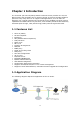
Chapter 1 Introduction The CT-5072T (TR-069 compliant) ADSL2+ Ethernet Router provides one 10/100 Ethernet port and one ADSL port for Internet access. It features TR-068 compliant panels for easy setup and use. It supports LAN applications, such as Video on Demand, over a regular telephone line at speeds of up to 24 Mbps. It has full routing capabilities and advanced security functions, such as VPNs (Virtual Private Networks) with PPTP pass-through, L2TP pass-through, IPSec pass-through and firewall. 1.
Chapter 2 Installation 2.1 Hardware Setup Follow the instructions below to complete the hardware setup. The picture below shows the back panel of the CT-5072T. Power ON Press the power button to the OFF position (OUT). Connect the power adapter to the power port. Attach the power adapter to a wall outlet or other AC source. Press the power button to the ON position (IN). If the Power LED displays as expected then the device is ready for setup (see section 2.2 LED Indicators).
2.2 LED Indicators The front panel LED indicators are shown below and explained in the following table. This information can be used to check the status of the device and its connections. LED Color LAN Green Mode On Off Blink On Green Off INTERNET Blink Red ADSL Green Green On On Off Blink On Off POWER Red On Function An Ethernet Link is established. An Ethernet Link is not established. Data transmitting or receiving over LAN. IP connected and no traffic detected.
Chapter 3 Web User Interface This section describes how to access the device via the web user interface (WUI) using an Internet browser such as Internet Explorer (version 5.0 and later). 3.1 Default Settings The factory default settings of this device are summarized below. LAN IP address: 192.168.1.1 LAN subnet mask: 255.255.255.
3.2 IP Configuration DHCP MODE When the CT-5072T powers up, the onboard DHCP server will switch on. Basically, the DHCP server issues and reserves IP addresses for LAN devices, such as your PC. To obtain an IP address from the DCHP server, follow the steps provided below. NOTE: The following procedure assumes you are running Windows XP. However, the general steps involved are similar for most operating systems (OS). Check your OS support documentation for further details.
STATIC IP MODE In static IP mode, you assign IP settings to your PC manually. Follow these steps to configure your PC IP address to use subnet 192.168.1.x. NOTE: The following procedure assumes you are running Windows XP. However, the general steps involved are similar for most operating systems (OS). Check your OS support documentation for further details.
3.3 Login Procedure Perform the following steps to login to the web user interface. NOTE: The default settings can be found in section 3.1. STEP 1: Start the Internet browser and enter the default IP address for the device in the Web address field. For example, if the default IP address is 192.168.1.1, type http://192.168.1.1. NOTE: For local administration (i.e. LAN access), the PC running the browser must be attached to the Ethernet, and not necessarily to the device. For remote access (i.e.
Chapter 4 Quick Setup After the first login, the Quick Setup screen will appear. It is the default screen when no connections exist. It allows for the configuration of connection settings. 4.1 Auto Quick Setup This function provides an automated process to quickly setup a WAN connection. The CT-5072T will auto-select the best available PVC profile, provided the ADSL link is up (see section 2.2). If you prefer manual connection setup, go to section 4.2.
4.2 Manual Quick Setup To setup the WAN connection manually, follow these instructions: STEP 1: Un-tick the DSL Auto-connect checkbox on the Quick Setup screen. Un-tick this checkbox to begin manual setup and display the following screen. STEP 2: Adjust the Virtual Path Identifier (VPI) and Virtual Channel Identifier (VCI) settings for the connection you wish to establish. You can also Enable Quality of Service (QoS) with its checkbox . Click Next to continue.
Click Next to continue… NOTE: The subsections that follow continue the ATM PVC setup procedure. Enter the appropriate settings for your service. Choosing different connection types will lead to a different sequence of setup screens. 4.2.1 PPP over ATM (PPPoA) and PPP over Ethernet (PPPoE) STEP 4: Enter the PPP settings as provided by your ISP. 13 Click Next to continue.
PPP SETTINGS The PPP Username, PPP password and the PPPoE Service Name entries are dependent on the particular requirements of the ISP. The user name can be a maximum of 256 characters and the password a maximum of 32 characters in length. For Authentication Method, choose from AUTO, PAP, CHAP, and MSCHAP. ENABLE FULLCONE NAT This option becomes available when NAT is enabled. Known as one-to-one NAT, all requests from the same internal IP address and port are mapped to the same external IP address and port.
USE STATIC IP ADDRESS Unless your service provider specially requires it, do not select this checkbox . If selected, enter the static IP address in the IP Address field. Also, don’t forget to adjust the IP configuration to Static IP Mode as described in section 3.2. RETRY PPP PASSWORD ON AUTHENTICATION ERROR Tick the checkbox to enable this function. ENABLE PPP DEBUG MODE When this option is selected, the system will put more PPP connection information into the system log.
ENABLE IGMP MULTICAST Tick the checkbox to enable Internet Group Membership Protocol (IGMP) multicast. IGMP is a protocol used by IP hosts to report their multicast group memberships to any neighboring multicast routers. ENABLE WAN SERVICE Tick the checkbox to enable WAN service. SERVICE NAME This is the WAN Service label. STEP 6: The Device Setup screen is used to configure LAN interface settings. The IP address and Subnet Mask define the location of the CT-5072T on the LAN.
STEP 7: Click Next to display the configuration summary. Click Save/Reboot if the settings are correct or click Back to modify these settings. After clicking Save/Reboot, the CT-5072T will save the configuration and reboot. 4.2.2 MAC Encapsulation Routing (MER) STEP 4: Enter the WAN IP settings provided by your ISP. Click Next to continue.
Select the Obtain an IP address automatically radio box NOTE: to enable DHCP. Assigning the default gateway or DNS server with static values will disable their automatic assignment from DHCP or another WAN connection. STEP 5: This screen provides access to Network Address Translation (NAT), IGMP Multicast, and WAN Service settings. Enable each service by selecting its checkbox . Click Next to continue. ENABLE NAT If the LAN uses private IP addresses, this checkbox must be selected.
requests from the same internal IP address and port are mapped to the same external IP address and port. An external host can send a packet to the internal host, by sending a packet to the mapped external address. ENABLE FIREWALL To enable IP packet filtering, tick this checkbox . The Advanced Setup Security IP Filtering option will appear on the main menu after reboot. Disable this function when not required for improved performance.
Select Enable DHCP Server Relay (if required), and enter the DHCP Server IP Address. This allows the CT-5072T to relay the DHCP packets to the remote DHCP server. The remote DHCP server will provide the IP address. NOTE: Enable DHCP Server Relay will not display if NAT is enabled. To configure a secondary IP address on the LAN, click the checkbox shown. STEP 7: Click Next to display the configuration summary. Click Save/Reboot if the settings are correct or click Back to modify these settings.
NOTE: Since DHCP is not supported over IPoA connections, the default gateway settings and DNS server addresses must be assigned manually. STEP 5: This screen provides access to Network Address Translation (NAT), IGMP Multicast, and WAN Service settings. Enable each service by selecting its checkbox . Click Next to continue. ENABLE NAT If the LAN uses private IP addresses, this checkbox must be selected. The NAT submenu will be added to the Advanced Setup menu after reboot.
ENABLE FIREWALL To enable IP packet filtering, tick this checkbox . The Advanced Setup Security IP Filtering option will appear on the main menu after reboot. Disable this function when not required for improved performance. ENABLE IGMP MULTICAST Tick the checkbox to enable Internet Group Membership Protocol (IGMP) multicast. IGMP is a protocol used by IP hosts to report their multicast group memberships to any neighboring multicast routers.
STEP 6: The Device Setup screen is used to configure LAN interface settings. The IP address and Subnet Mask define the location of the CT-5072T on the LAN. To auto-assign IP addresses, DNS server and default gateway to LAN devices, select the Enable DHCP server radio button. You must also enter the start and end IP address, Subnet Mask and DHCP leased time. Select Enable DHCP Server Relay (if required), and enter the DHCP Server IP Address.
STEP 7: Click Next to display the configuration summary. Click Save/Reboot if the settings are correct or click Back to modify these settings. After clicking Save/Reboot, the CT-5072T will save the configuration and reboot. 4.2.4 Bridging STEP 4: To enable bridge service, tick the checkbox and enter a service name. Click Next to continue.
STEP 5: The Device Setup screen is used to configure LAN interface settings. Enter an IP Address and Subnet Mask for the CT-5072T LAN interface. STEP 6: Click Next to display the configuration summary. Click Save/Reboot if the settings are correct or click Back to modify these settings. After clicking Save/Reboot, the router will save the configuration and reboot.
Chapter 5 Device Information The web user interface is divided into two windowpanes, the main menu (at left) and the display screen (on the right). The main menu has several options and selecting each of these options opens a submenu with more selections. NOTE: The menu items shown are based upon the configured connection(s) and user account privileges. For example, if NAT and Firewall are enabled, the main menu will display the NAT and Security submenus.
Heading Description VPI/VCI ATM VPI (0-255) / VCI (32-65535) VLAN Mux Shows 802.1Q VLAN ID Con.
Heading Description Interface LAN interface(s) Received/Transmitted: 5.2.2 - Bytes Pkts Errs Drops Number Number Number Number of of of of Bytes Packets packets with errors dropped packets WAN Statistics This screen shows data traffic statistics for each WAN interface. Heading Description Service WAN service label VPI/VCI ATM Virtual Path/Channel Identifiers Protocol Connection type (e.g. PPPoE, IPoA, Bridge) Interface WAN interfaces Received/Transmitted 5.2.
ATM Interface Statistics Heading Description In Octets Number of received octets over the interface Out Octets Number of transmitted octets over the interface In Errors Number of cells dropped due to uncorrectable HEC errors In Unknown Number of received cells discarded during cell header validation, including cells with unrecognized VPI/VCI values, and cells with invalid cell header patterns. If cells with undefined PTI values are discarded, they are also counted here.
Heading Description In Errors Number of received AAL5/AAL0 CPCS PDUs received that contain an error. These errors include CRC-32 errors. Out Errors Number of received AAL5/AAL0 CPCS PDUs that could not be transmitted due to errors. In Discards Number of received AAL5/AAL0 CPCS PDUs discarded due to an input buffer overflow condition.
5.2.4 ADSL Statistics The ADSL Statistics screen is shown below with a reference table that follows. Click the Reset Statistics button to refresh this screen. Field Mode Description G.Dmt, G.lite, T1.
Field Type Line Coding Status Link Power State Description Channel type Interleave or Fast Trellis On/Off Lists the status of the DSL link Link output power state. SNR Margin (dB) Attenuation (dB) Signal to Noise Ratio (SNR) margin Estimate of average loop attenuation in the downstream direction. Total upstream output power The sync rate you would obtain. Current sync rate. The rate of signal degradation between the DSLAM and the modem. Modem signal strength.
Within the ADSL Statistics window, a Bit Error Rate (BER) test can be started using the ADSL BER Test button. A small window will open when the button is pressed; it will appear as shown below. Click Start to start the test or Close. If the test is successful, the pop-up window will display as follows.
5.3 Route Choose Route to display the routes that the CT-5072T has found. Field Description Destination Destination network or destination host Gateway Next hub IP address Subnet Mask Subnet Mask of Destination Flag U: route is up !: reject route G: use gateway H: target is a host R: reinstate route for dynamic routing D: dynamically installed by daemon or redirect M: modified from routing daemon or redirect Metric The 'distance' to the target (usually counted in hops).
5.4 ARP Click ARP to display the ARP information. Field IP address Flags HW Address Device Description Shows IP address of host pc Complete, Incomplete, Permanent, or Publish Shows the MAC address of host pc Shows the connection interface 5.5 DHCP Click DHCP to display all DHCP Leases.
Chapter 6 Advanced Setup This chapter explains the following screens: 6.1 WAN 6.2 LAN 6.3 NAT 6.4 Security 6.5 Parental Control 6.6 Quality of Service 6.7 Routing 6.8 DNS 6.9 DSL 6.10 Certificate 6.1 WAN This screen allows for the configuration of WAN interfaces. To Add a new WAN connection, click the Add button. To edit an existing connection, click the Edit button next to the connection. To complete the Add or Edit go to STEP 2 in section 4.2.
Heading Description Interface Name of the interface for WAN Protocol Shows the connection type Igmp Shows Internet Group Management Protocol (IGMP) status Nat Shows Network Address Translation (NAT) status Firewall Shows the status of Firewall QoS Shows Quality of Service (QoS) status State Shows the connection state of the WAN connection Remove Used to select connections for removal Edit Used to edit connections 6.2 LAN From this screen, LAN interface settings can be configured.
DHCP Server: To enable DHCP, select Enable DHCP server and enter Start and End IP addresses and the Leased Time. This setting configures the router to automatically assign IP, default gateway and DNS server addresses to every PC on your LAN. DHCP Server Relay: Enable with checkbox and enter DHCP Server IP address. This allows the Router to relay the DHCP packets to the remote DHCP server. The remote DHCP server will provide the IP address.
6.3 NAT To display this option, NAT must be enabled in at least one PVC shown on the Advanced Setup - WAN screen. (NAT is not an available option in Bridge mode) 6.3.1 Virtual Servers Virtual Servers allow you to direct incoming traffic from the WAN side (identified by Protocol and External port) to the Internal server with private IP addresses on the LAN side. The Internal port is required only if the external port needs to be converted to a different port number used by the server on the LAN side.
Consult the table below for field and header descriptions. Field/Header Description Select a Service Or Custom Server User should select the service from the list. Or User can enter the name of their choice. Server IP Address Enter the IP address for the server. External Port Start Enter the starting external port number (when you select Custom Server). When a service is selected, the port ranges are automatically configured.
Consult the table below for field and header descriptions. Field/Header Description Select an Application Or Custom Application User should select the application from the list. Or User can enter the name of their choice. Trigger Port Start Enter the starting trigger port number (when you select custom application). When an application is selected, the port ranges are automatically configured. Trigger Port End Enter the ending trigger port number (when you select custom application).
6.3.3 DMZ Host The DSL router will forward IP packets from the WAN that do not belong to any of the applications configured in the Virtual Servers table to the DMZ host computer. To Activate the DMZ host, enter the DMZ host IP address and click Save/Apply. To Deactivate the DMZ host, clear the IP address field and click Save/Apply. 6.3.
6.4 Security To display this function, you must enable the firewall feature in WAN Setup. For detailed descriptions, with examples, please consult Appendix A – Firewall. 6.4.1 IP Filtering This screen sets filter rules that limit IP traffic (Outgoing/Incoming). Multiple filter rules can be set and each applies at least one limiting condition. For individual IP packets to pass the filter all conditions must be fulfilled. NOTE: This function is not available when in bridge mode.
Field Description Filter Name The filter rule label Protocol TCP, TCP/UDP, UDP, or ICMP. Source IP address Enter source IP address. Source Subnet Mask Enter source subnet mask. Source Port (port or port:port) Enter source port number or range. Destination IP address Enter destination IP address. Destination Subnet Mask Enter destination subnet mask. Destination Port (port or port:port) Enter destination port number or range.
Under WAN Interfaces, select the PVCs (All routing modes with firewall ON) where the filter rule will apply. You may select all PVCs or just a subset. Filter rules are arranged by PVC as shown under the VPI/VCI heading on the previous screen. 6.4.2 MAC Filtering NOTE: This option is only available in bridge mode. Other modes (i.e. PPPoE/A, IPoA, MER) use IP Filtering (pg.43) to perform a similar function. Each network device has a unique 48-bit MAC address.
Consult the table below for detailed field descriptions. Field Description Protocol Type PPPoE, IPv4, IPv6, AppleTalk, IPX, NetBEUI, IGMP Destination MAC Address Defines the destination MAC address Source MAC Address Defines the source MAC address Frame Direction Select the incoming/outgoing packet interface WAN Interfaces Applies the filter to selected bridge PVCs. These rules are arranged according to bridge PVC, as shown under the VPI/VCI heading on the previous screen. 6.
See below for field descriptions. Click Save/Apply to add a time restriction. User Name: A user-defined label for this restriction. Browser's MAC Address: MAC address of the PC running the browser. Other MAC Address: MAC address of another LAN device. Days of the Week: The days the restrictions apply. Start Blocking Time: The time the restrictions start. End Blocking Time: The time the restrictions end. 6.5.
Enter the URL address and port number then click Save/Apply to add the entry to the URL filter. URL Addresses begin with “www”, as shown in this example. A maximum of 100 entries can be added to the URL Filter list. Tick the Exclude radio button to deny access to the websites listed. Tick the Include radio button to restrict access to only those listed websites. 6.6 Quality of Service NOTE: QoS must be enabled in at least one PVC to display this option.
QoS and DSCP Mark are defined as follows: Quality of Service (QoS): This provides different priority to different users or data flows, or guarantees a certain level of performance to a data flow in accordance with requests from Queue Prioritization. Default Differentiated Services Code Point (DSCP) Mark: This specifies the per hop behavior for a given flow of packets in the Internet Protocol (IP) header that do not match any other QoS rule. 6.6.
Queue Configuration Status: Enable/Disable the Queue entry. Queue: Assign the entry to a specific network interface (QoS must be enabled). Queue Precedence: Configure precedence for the Queue entry. Lower integer values for precedence imply higher priority for this entry relative to others. 6.6.3 QoS Classification The network traffic classes are listed in the following table. Click Add to configure a network traffic class rule and Save/Apply to activate it.
Field Description Traffic Class Name Enter a name for the traffic class. Rule Order Last or null are the only options. Rule Status Disable or enable the rule. Assign Classification Queue The queue configurations are presented in this format: “Interfacename&Prece P&Queue Q” where P and Q are the Precedence and Queue Key values for the corresponding Interface as listed on the Queue Config screen.
Field Description SET-1 Protocol TCP, TCP/UDP, UDP, or ICMP. Differentiated Services Code Point (DSCP) Check The selected Code Point gives the corresponding priority to the packets that satisfies the rules set below. Static IP or DHCP ID drop-down box Select IP Address, Vendor Class ID (DHCP Option 60), or User Class ID (DHCP Option 77) Source IP Address Enter the source IP address. Source Subnet Mask Enter the subnet mask for the source IP address.
6.7.1 Default Gateway If the Enable Automatic Assigned Default Gateway checkbox is selected, the router will accept the first received default gateway assignment from one of the PPPoA, PPPoE or MER (DHCP enabled) PVC(s). If the checkbox is not selected, enter the static default gateway AND/OR a WAN interface. Click Save/Apply. NOTE: After enabling the Automatic Assigned Default Gateway, the device must be rebooted to activate the assigned default gateway. 6.7.
Click the Add button to display the following screen. Enter Destination Network Address, Subnet Mask, Gateway IP Address, and/or WAN Interface. Then click Save/Apply to add the entry to the routing table. 6.7.3 RIP To activate RIP, select the Enabled radio button for Global RIP Mode. To configure an individual interface (PVC), select the desired RIP Version and Operation, and then select the Enabled checkbox for that interface (PVC).
6.8 DNS 6.8.1 DNS Server If the Enable Automatic Assigned DNS checkbox is selected, this router will accept the first received DNS assignment from one of the DHCP enabled PVC(s). If the checkbox is not selected, enter the primary and optional secondary DNS server IP addresses. Click Save to save the new configuration. NOTE: You must reboot the router to make the new configuration effective. 6.8.
To add a dynamic DNS service, click Add. The following screen will display. Consult the table below for field descriptions.
6.9 DSL The DSL Settings screen allows for the selection of DSL modulation modes. For optimum performance, the modes selected should match those of your ISP. DSL Mode Data Transmission Rate - Mbit/s (Megabits per second) G.Dmt Downstream: 12 Mbit/s Upstream: 1.3 Mbit/s G.lite Downstream: 4 Mbit/s Upstream: 0.5 Mbit/s T1.413 Downstream: 8 Mbit/s Upstream: 1.
6.10 Certificate A certificate is a public key, attached with its owner’s information (company name, server name, personal real name, contact e-mail, postal address, etc) and digital signatures. There will be one or more digital signatures attached to the certificate, indicating that these entities have verified that this certificate is valid. 6.10.1 Local CREATE CERTIFICATE REQUEST Click Create Certificate Request to generate a certificate-signing request.
Field Description Certificate Name A user-defined name for the certificate. Common Name Usually, the fully qualified domain name for the machine. Organization Name The exact legal name of your organization. Do not abbreviate. State/Province Name The state or province where your organization is located. It cannot be abbreviated. Country/Region Name The two-letter ISO abbreviation for your country.
6.10.2 Trusted CA CA is an abbreviation for Certificate Authority, which is a part of the X.509 system. It is itself a certificate, attached with the owner information of this certificate authority; but its purpose is not encryption/decryption. Its purpose is to sign and issue certificates, in order to prove that these certificates are valid. Click Import Certificate to paste the certificate content of your trusted CA.
Chapter 7 Diagnostics The Diagnostics menu provides feedback on the connection status of the CT-5072T. The basic tests (no PVC configured) are described in the table below. If a test displays a fail status, click the Test button to retest and confirm the error. If the test continues to fail, click Help and follow the troubleshooting procedures provided. Test Description ENET Connection Pass: Indicates that the CT-5072T has detected the Ethernet interface on your computer.
Chapter 8 Management The Management menu has the following maintenance functions and processes: 8.1 Settings 8.2 System Log 8.3 SNMP Agent 8.4 TR-069 Client 8.5 Internet Time 8.6 Access Control 8.7 Update Software 8.8 Save and Reboot 8.1 Settings This includes Backup Settings, Update Settings, and Restore Default screens. 8.1.1 Backup Settings To save the current configuration to a file on your PC, click Backup Settings. You will be prompted for a location of the backup file.
8.1.3 Restore Default Click Restore Default Settings to restore the CT-5072T to factory default settings. After Restore Default Settings is clicked, the following screen appears. Close the browser and wait for 2 minutes before reopening it. It may also be necessary, to reconfigure your PC IP configuration to match your new settings. NOTE: This entry has the same effect as the Reset button. The CT-5072T board hardware and the boot loader support the reset to default.
8.2 System Log This function allows a system log to be kept and viewed upon request. Follow the steps below to configure, enable, and view the system log. STEP 1: Click Configure System Log, as shown below (circled in Red). STEP 2: Select desired options and click Save/Apply. Consult the table below for detailed descriptions of each system log option. Option Description Log Indicates whether the system is currently recording events. The user can enable or disable event logging.
Option Description Log level Allows you to configure the event level and filter out unwanted events below this level. The events ranging from the highest critical level “Emergency” down to this configured level will be recorded to the log buffer on the CT-5072T SDRAM. When the log buffer is full, the newer event will wrap up to the top of the log buffer and overwrite the old event. By default, the log level is “Debugging”, which is the lowest critical level.
8.3 SNMP Agent Simple Network Management Protocol (SNMP) allows a management application to retrieve statistics and status from the SNMP agent in this device. Select the Enable radio button, configure options, and click Save/Apply to activate SNMP. Options Description SNMP Agent Use the radio buttons to Enable or Disable the SNMP Agent Read Community Default is “public” Set Community Default is “private” System Name Default determined from the hostname.
Option Description Inform Disable/Enable TR-069 client on the CPE. Inform Interval The duration in seconds of the interval for which the CPE MUST attempt to connect with the ACS and call the Inform method. ACS URL URL for the CPE to connect to the ACS using the CPE WAN Management Protocol. This parameter MUST be in the form of a valid HTTP or HTTPS URL. An HTTPS URL indicates that the ACS supports SSL.
8.5 Internet Time This option automatically synchronizes the router time with Internet timeservers. To enable time synchronization, tick the corresponding checkbox , choose your preferred time server(s), select the correct time zone offset, and click Save/Apply. NOTE: Internet Time must be activated to use Parental Control (page 46). In addition, this menu item is not displayed when in Bridge mode since the router would not be able to connect to the NTP timeserver. 8.6 Access Control 8.6.
NOTES: The WAN column only appears if a PVC connection is configured. For a quick introduction to SSH clients consult Appendix C. 8.6.2 IP Addresses This option limits access to the router by IP address. When Access Control Mode is enabled, only the IP addresses listed here can access the router. Before enabling Access Control Mode, configure the IP addresses by clicking the Add button. Enter the IP address and subnet mask, and select an interface.
8.6.3 Passwords This screen is used to configure the user account access passwords for the device. Access to the CT-5072T is controlled through the following three user accounts: root - this has unrestricted access to change and view the configuration. support - used for remote maintenance and diagnostics of the router user - this has limited access. This account can view configuration settings and statistics, as well as, update the router firmware.
STEP 1: Obtain an updated software image file from your ISP. STEP 2: Enter the path and filename of the firmware image file in the Software File Name field or click the Browse button to locate the image file. STEP 3: Click the Update Software button once to upload and install the file. NOTE: The update process will take about 2 minutes to complete. The device will reboot and the browser window will refresh to the default screen upon successful installation.
Appendix A – Firewall STATEFUL PACKET INSPECTION Refers to an architecture, where the firewall keeps track of packets on each connection traversing all its interfaces and makes sure they are valid. This is in contrast to static packet filtering which only examines a packet based on the information in the packet header. DENIAL OF SERVICE ATTACK Is an incident in which a user or organization is deprived of the services of a resource they would normally expect to have.
Example 2: Filter Name Protocol Source Address Source Subnet Mask Source Port Dest. Address Dest. Subnet Mask Dest. Port : : : : : : : : Out_Filter2 UDP 192.168.1.45 255.255.255.0 5060:6060 172.16.13.4 255.255.255.0 6060:7070 This filter will drop all UDP packets coming from the LAN with IP Address / Subnet Mask of 192.168.1.45/24 and a source port range of 5060 to 6060, destined to 172.16.13.4/24 and a destination port range of 6060 to 7070.
Example 2: Filter Name Protocol Source Address Source Subnet Mask Source Port Dest. Address Dest. Sub. Mask Dest. Port : : : : : : : : In_Filter2 UDP 210.168.219.45 255.255.0.0 5060:6060 192.168.1.45 255.255.255.0 6060:7070 This rule will ACCEPT all UDP packets coming from WAN interface mer_0_35/nas_0_35 with IP Address/Subnet Mask 210.168.219.45/16 and a source port in the range of 5060 to 6060, destined to 192.168.1.45/24 and a destination port in the range of 6060 to 7070.
Source MAC Address : 00:34:12:78:90:56 Frame Direction : WAN => LAN WAN Interface Selected : br_0_34/nas_0_34 Addition of this rule forwards all PPPoE frames going from WAN to LAN with a Destination MAC Address of 00:12:34:56:78 and Source MAC Address of 00:34:12:78:90:56 on the br_0_34 WAN interface. All other frames on this interface are dropped.
Appendix B – Pin Assignments LINE PORT (RJ11) Pin Definition Pin Definition 1 - 4 ADSL_TIP 2 - 5 - 3 ADSL_RING 6 - LAN Port (RJ45) Pin Definition Pin Definition 1 Transmit data+ 5 NC 2 Transmit data- 6 Receive data- 3 Receive data+ 7 NC 4 NC 8 NC 76
Appendix C – Specifications Hardware Interface RJ-11 X 1 for ADSL2+ RJ-45 X 1 for LAN Power Switch X 1 Reset Button X 1 WAN Interface ITU-T G.992.5/G.992.3/G.992.1, ANSI T1.413 Issue 2 G.992.5 (ADSL2+) ........Downstream : 24 Mbps Upstream : 1.3 Mbps G.992.3 (ADSL2)...........Downstream : 12 Mbps Upstream : 1.3 Mbps G.DMT .........................Downstream : 8 Mbps Upstream : 832 Kbps Annex M LAN Interface Suport IEEE 802.3 and IEEE 802.
NAT/NAPT Support Port Triggering and Port forwarding Symmetric port-overloading NAT, Full-Cone NAT VPN Passthrough (PPTP, L2TP, IPSec) Security Functions Authentication protocol: PAP, CHAP TCP/IP/Port filtering rules, Packet and MAC address filtering SSH, Port Triggering/Forwarding, Access Control, DoS Protection Three level login including local admin, local user and remote technical support access QoS ............................................................
Appendix D – SSH Client Unlike Microsoft Windows, Linux OS has a ssh client included. For Windows users, there is a public domain one called “putty” that can be downloaded from here: http://www.chiark.greenend.org.uk/~sgtatham/putty/download.html To access the ssh client you must first enable SSH access for the LAN or WAN from the Management Access Control Services menu in the web user interface. To access the router using the Linux ssh client For LAN access, type: ssh -l root 192.168.1.