WAP-5940 Wireless Video Bridge User Manual 261097-022 Version A1.
Preface This manual provides information related to the installation and operation of this device. The individual reading this manual is presumed to have a basic understanding of telecommunications terminology and concepts. If you find the product to be inoperable or malfunctioning, please contact technical support for immediate service by email at INT-support@comtrend.com For product update, new product release, manual revision, or software upgrades, please visit our website at http://www.comtrend.
Copyright Copyright©2016 Comtrend Corporation. All rights reserved. The information contained herein is proprietary to Comtrend Corporation. No part of this document may be translated, transcribed, reproduced, in any form, or by any means without prior written consent of Comtrend Corporation.
Table of Contents CHAPTER 1 INTRODUCTION ........................................................................................................... 4 CHAPTER 2 INSTALLATION............................................................................................................. 5 2.1 HARDWARE SETUP ........................................................................................................................... 5 2.2 LED INDICATORS................................................................
Chapter 1 Introduction The WAP-5940 is an 802.11ac 4T4R wireless video bridge, with two Giga Ethernet ports. WAP-5940 performs AP to transmission package TCP/UDP to client, also supporting station mode, receiving packets and forwarding to the Ethernet port. WAP-5940 has a high power wireless design which supports 802.11ac 5Ghz band 4T4R and is backward compatible 802.11n, 802.11a.
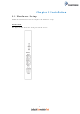
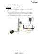
Chapter 2 Installation 2.1 Hardware Setup Follow the instructions below to complete the hardware setup. BACK PANEL The figure below shows the back panel of the device.
Power ON Press the power button to the OFF position (OUT). Connect the power adapter to the power port. Attach the power adapter to a wall outlet or other AC source. Press the power button to the ON position (IN). If the Power LED displays as expected then the device is ready for setup (see section 2.2 LED Indicators). Caution 1: If the device fails to power up, or it malfunctions, first verify that the power cords are connected securely and then power it on again.
2.2 LED Indicators The front panel LED indicators are shown below and explained in the following table. This information can be used to check the status of the device and its connections.
2.3 Initial Device Setup Device Setup 1. Setup the first Wireless Video Bridge by plugging in the power adapter and press the Power Button to the ON position (IN). Set the Wireless Video Bridge to AP Mode by sliding the AP/Station Switch to the up position. 2. Connect the Wireless Video Bridge to a Network Device (Gateway, Router, etc.) with an Ethernet (RJ-45) cable. You can use either Ethernet ports of the Wireless Video Bridge to make this connection. 3.
4. After you select station mode thus two Ethernet ports (ETH1, ETH2) are LAN side.
Chapter 3 Web User Interface This section describes how to access the device via the web user interface (WUI) using an Internet browser such as Internet Explorer (version 6.0 and later). 3.1 Default Settings The factory default settings of this device are summarized below. • • • • LAN IP address AP: 10.0.0.2 LAN IP address STA: 10.0.0.10 LAN subnet mask: 255.255.255.
3.2 IP Configuration STATIC IP MODE In static IP mode, you assign IP settings to your PC manually. Follow these steps to configure your PC IP address to use subnet 10.0.0.x. NOTE: The following procedure assumes you are running Windows. However, the general steps involved are similar for most operating systems (OS). Check your OS support documentation for further details.
3.3 Login Procedure Perform the following steps to login to the web user interface. NOTE: The default settings can be found in section 3.1 Default Settings. STEP 1: Start the Internet browser and enter the default IP address for the device in the Web address field. For example, if it is the AP device default IP is 10.0.0.2, type http://10.0.0.2 STEP 2: A dialog box will appear, such as the one below. Enter the default username and password, as defined in section 3.1 Default Settings.
STEP 3: After successfully logging in for the first time (AP device in this example), you will reach the Status - Device screen AP (Access Point) shown here.
Chapter 4 Status 4.1 Status - Device This screen shows the status of the device.
Uptime Displays the There are two types of uptime of the display, one kind is device minutes and days, another kind is XX:XX(hours:minutes) Device Mode AP or STA mode Access Point(AP) Device Acts as Access Station(STA) Point or Station. The [X] indicates the current device mode.
4.2 Status – Wireless This screen shows the wireless status of the device in AP mode. 4.2.
Wireless Band Current system 802.11a or Band 802.11an or 802.11ac Bandwidth Per the 802.11a or 802.11an supports 802.11n and is backward compatible with 802.11a 20 MHz 20 MHz operation 40 MHz 40 MHz operation 80MHz 80 MHz operation 802.11an or 802.11ac standard Per 802.11an or 802.11ac standard Per the 802.
Packets Wireless packets Transmitted transmitted Successfully Bytes Total bytes Transmitted transmitted successfully This screen shows the information of all station devices which are connecting with the wifi0 of the AP.
4.2.2 STA Mode This screen shows the wireless status of the device that acts as a STA. This STA mode is mainly with other client bridge, Not directly used as a client. Menu Item Description Options Detail Device Mode AP or STA mode Access Point(AP) Device Acts as Station (STA) Access Point or Station Wireless Band Current system 802.11a or Band 802.11an or 802.11ac Bandwidth Per the 802.11a or 20 MHz 802.11an or 19 802.11an supports 802.11n and is backward compatible with 802.
802.11ac standard Per 802.11an or 40 MHz 40 MHz operation 80MHz 80 MHz operation 802.11ac standard Per the 802.11ac standard AP Mac Address The current In AP mode, it will (BSSID) associated BSSID be the same as the of the Wi-Fi system Wireless MAC address Channel Available 5Ghz 36-48, 149-165 5.150-5.250, channels based on 5.725-5.850 GHz region setting are the supported frequency ranges Association The connected The number of Status devices number devices connecting to the AP.
Bytes Received The total bytes received successfully Packets Wireless packets Transmitted transmitted Successfully Bytes Total bytes Transmitted transmitted successfully 21
4.3 Status – Networking This screen shows the status of the networking. Menu Item Description Options Detail IP Address The IP Address of Logged into the web the system GUI with this IP address. It can be changed in the Config Networking page.
Wireless MAC This is the IEEE The WLAN MAC Address compliant MAC address address of the Wi-Fi interface BSSID The current In AP mode: this will associated BSSID be the SAME as the of the Wi-Fi system Wireless MAC address. In STA mode and associated to an AP: this will be the value of the AP’s MAC address. If the STA is not associated, this will state: “Not-Associated”.
4.4 Status – WDS This screen shows the status of the WDS links. This typical WDS link status includes: • The interface name of the WDS link, the name is managed by the system automatically, usually it is: WDS0/WDS1/WDS2…so on. • The WDS peer MAC address of the opposite side, this MAC address is same as the address which you are using when creating WDS links. • The WDS link quality.
4.5 Status – MBSS Displays the information of multiple Basic Service Set Identifiers (BSSIDs) created on the device: SSID, Broadcast, Association count and details of the station connected. This option is not available if the device is configured as a STA. For instructions on setting up WAP-5940 as a WDS using AP mode, please refer to Appendix B. Menu Item Description SSID SSID of the MBSS Options Detail This will be the SSID of the wireless network.
number client which are connected to the Virtual AP 26
Chapter 5 Config 5.1 Config – Wireless This screen has two tab pages, “Basic” and “Advanced”.
ESSID Channel SSID of the AP Available 5Ghz Can be set to This will be the desired SSID SSID of the name wireless network. 36-48, 149-165 5.150-5.250, channels based on 5.725-5.850 GHz region setting are the supported frequency ranges PMF Encryption Protected Sets the 802.11w / Management PMF capability. Frames Applies to AP 802.
Menu Item Description Options Detail Wireless Band Frequency Band to 802.11a 802.11a 5 GHz be used operation 802.11an 802.11an 5 GHz operation 802.11ac 802.11ac 5 GHz operation Bandwidth Per the 802.11a or 20 MHz 20 MHz operation 40 MHz 40 MHz operation 80MHz 80 MHz operation 802.11an or 802.11ac standard Per the 802.11an or 802.11ac standard Per the 802.
standard NSS The maximum Auto number of spatial 1 streams 2 3 4 Tx Rate Transmitted data Not supported for rate 802.11a standard Auto or MCS0 Auto Rate Control, ~MCS76 for MCS 0-76 802.11an standard Only Auto option available for 802.11ac standard when NSS is set to Auto. When NSS is not set to Auto, MCS0~MCS9 options are available.
should check for buffered data awaiting pickup on the access point. The value should between 1 and 15. Short GI Guard Intervals Checked The 802.11n draft specifies two guard intervals: 400ns (short) and 800ns (long). The GI is 400ns.
5.2 Config – WPS Connect to without selecting an SSID and inputting a Passphrase. Menu Item Description Options Detail WPS State Set WPS states Disabled WPS disabled Not configured WPS enabled User can remotely change AP's wireless settings…SSID, Encryption and Passphrase for example.
Configured User needs to fill certain parameters to start WPS connection WPS PBC WPS push button Push button to start WPS connection WPS PIN For Web UI pin Character string WPS pin mode This will be the PIN used for Web UI WPS pin mode. WPS AP PIN Client must have same PIN within 2 minutes. It is recommended to use the external WPS push button on the device.
5.3 Config – MAC Filter This screen shows the MAC addresses filtering configurations that are used for the AP. Menu Item Description Wifi Interface Real wireless device Options Detail NONE The AP can block a name and MAC Address in CPE MAC Address The device filter Filtering MAC address selected station from associating based on its MAC (hardware interface) address.
“NONE”= Disable MAC address filtering.
5.4 Config – Networking These screens show the networking configuration.
Static IP Menu Item Description Options Detail DHCP or Static Set the network DHCP The device will try IP configuration to to get its IP address DHCP or Static IP with DHCP from a device like a router Static IP The device will use the static IP address IP Address The IP Address of This can be the system changed from this interface, by editing this field.
address is not allowed to change. CAUTION: After selecting “Save”, the IP Address will change IMMEDIATELY. The Web UI must be pointed at the new address in order to continue your Web UI Session. Netmask Netmask of the IP address Ethernet MAC This is the IEEE The internal Address compliant MAC network bridge address of the uses this MAC Ethernet interface address. This cannot be changed. Wireless MAC This is the IEEE The WLAN MAC Address compliant MAC address.
5.5 Config – WDS This screen shows the configuration of the WDS links. This option is not available if the device is configured as a STA.
address on the opposite side Passphrase 64 ASCII PSK Wi-Fi devices can see the SSID in scan. Now the passphrase string is displayed as "*******" instead.
5.6 Config – MBSS One can create multiple Basic Service Set Identifiers (BSSIDs) on a device initially configured as an access point (AP). This capability is not available on a device configured as a STA. The first step in creating an additional BSSID is to create the wireless interface device for that BSSID.
Menu Item Description SSID SSID of the MBSS Options Detail This will be the SSID of the wireless network. VLAN Virtual Lan for different 1-4096 interface Broadcast Enabled or disabled Checked SSID will be broadcast Unchecked Wi-Fi devices can see SSID broadcast the SSID in scan Priority The priority is used to differentiate traffic between different 0 is highest priority. 3 is lowest priority. SSIDs PMF Protected Management Sets the 802.11w / Frames PMF capability.
Menu Item Description Options Enable Enable TR-069 Select to enable daemon connection to ACS Disable Disable TR-069 Select to disable daemon connection to ACS URL IP address and port the device uses to connect to the ACS Username Username used to authenticate on ACS 43 Detail
Password Password used to authenticate on ACS Periodic Inform Activate / Unit is Deactivate the info second(s) message to ACS server Interval Periodic time interval of sending the info message Connection Request URL The path for the connection from the ACS to the CPE. It is recommended to keep the default setting.
ACS which support STUN Username Username used to authenticate on ACS which support STUN Password Password used to authenticate on ACS which support STUN Maximum Keep The maximum Unit is Alive Period connect duration to second(s) the ACS server Minimum Keep The minimum Unit is Alive Period connect duration to second(s) the ACS server 45
Chapter 6 Tools 6.1 Tools – Log This page has the ability to directly view the PHY statistics of the device. Pressing the “Start” button will start a 10 second polling log. This data can be useful to assist in debugging the system. After selecting “Start”, the page will look similar to the image above. The logging will stop after pressing the “Stop” button. If the IP address is changed or if the device is shut off, this page will give an error message if logging was in progress.
Metric Description Comments Tstamp This is the system time of the measurement taken from the internal system clock RxPkts This represents the number of packets that were successfully received over 1 second intervals. Each line represents 1 second of time. RxGain This is the higher receiver The maximum value of gain value that was RxGain is 62 recorded on successfully received packets during this measurement interval. If no packets were received, this may be an invalid number.
Defers This number counts the Defers are common in busy number of times an WiFi environments attempted transmission was deferred due to the medium being busy. This is helpful in determining if an environment is very busy. Tout This is an indicator of Tx Timeouts are not common. packet timeout The Packet could not find a time slot to transmit.
6.2 Tools – Admin This page is for administration of the user passwords.
6.3 Tools – Restore The Tools Restore page is for users to restore all the configurations of the device to factory defaults. There is also the option to restore the configuration files and reboot whilst retaining the IP settings. The Restore function also restores the password of the login user.
Chapter 7 System 7.1 System – Upgrade The System Upgrade page is for users to update the firmware on the device. This page will upload a binary image file. Please use bin file to upgrade which is named like “WAP-5940-EM51-3671361CTU-CXX_RXX.bin”. When you select the file and click “Upgrade”, the “Upgrade” button will be disabled and the page will display “Loading the image file......Please wait”, please wait for 2 minutes. Please be patient and do not power off the unit during this process.
When the firmware has been upgraded successfully, you will be automatically directed to the reboot page.
7.2 System – Reboot The System Reboot page is for users to reboot the device.
Appendix A - Specifications Hardware Interface • • • • • • • AP/Station Switch x 1 RJ-45 X 2 for Giga Ethernet port Reset Button X 1 WPS button X 1 4x internal MIMO antenna Power switch X 1 Power Jack X 1 Standard • • • • • • • • • 802.11a/n/ac 802.11i (WEP, WPA/WPA2, RADIUS) 802.11d 802.11e (WMM, WMM-PS) 802.11w 802.11h 802.11k 802.11r 802.11s (Draft) Rates are for 256 QAM • • • 80MHz: 1.7Gbps 40MHz: 800Mbps 20MHz: 346.8Mbps Environment Condition Operating temperature ................................
Appendix B - AP / Station After you select AP mode thus the Ethernet port (ETH1) will be WAN port, another Ethernet port (ETH2) is LAN side.
After you select station mode thus two Ethernet ports (ETH1, ETH2) are LAN side.
Warnings Guide FCC Statements This equipment has been tested and found to comply with the limits for a Class B digital device, pursuant to Part 15 of the FCC Rules. These limits are designed to provide reasonable protection against harmful interference in a residential installation. This equipment generates, uses and can radiate radio frequency energy and, if not installed and used in accordance with the instructions, may cause harmful interference to radio communications.
Users should also be advised that high-power radars are allocated as primary users (i.e. priority users) of the bands 5250-5350 MHz and 5650-5850 MHz and that these radars could cause interference and/or damage to LE-LAN devices. Other Statements This device and its antenna(s) must not be co-located or operating in conjunction with any other antenna or transmitter.