
Owner's manual


Appendix A. Connectors 27
Appendix A. Connectors
This section contains information about the standard connectors on the ATS-LNX.
For connector information for the optional SERIAL PORTS 1-8 connector, see the
section that discusses the PCMCIA option.
VGA Connector
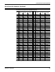
This table illustrates the 15-pin female VGA connector pinouts.
PS/2 Keyboard and Mouse Connectors
This table illustrates the DIN 6-pin (PS/2) keyboard and mouse connector pinouts.
Ethernet Connectors
This table illustrates the RJ45 LAN connector pinouts.
Pin Signal Pin Signal Pin Signal
1 Red 6 Ground 11 Not connected
2 Green 7 Ground 12 DDCDAT
3Blue 8Ground 13HSYNC
4 Not connected 9 Not connected 14 VSYNC
5 Ground 10 Ground 15 DDCCLK
Pin Signal Pin Signal
1 Keyboard Data 4 +5V
2 Mouse Data 5 Keyboard Clock
3 Ground 6 Mouse Clock
Pin Signal Pin Signal
1 TX+ 5 Not connected
2 TX- 6 RX-
3 RX+ 7 Not connected
4 Not connected 8 Not connected