Installation and Configuration Guide
Trademark Notices Comtrol and DeviceMaster are trademarks of Comtrol Corporation. RocketPort is a registered trademark of Comtrol Corporation. Windows registered trademark of Microsoft Corporation. Other product names mentioned herein may be trademarks and/or registered trademarks of their respective owners. URL References All URLs in this document worked at the time of publication.
Table of Contents Installation and Setup ........................................................................................................................ 5 Audience .......................................................................................................................................................... 5 Product Overview .........................................................................................................................................
Table of Contents Troubleshooting and Technical Support ..................................................................................... 53 Troubleshooting Checklist ........................................................................................................................ 53 Enabling the Event Viewer ....................................................................................................................... 54 Using the Recovery CD .............................................
Installation and Setup This section discusses the following topics: • Audience • Product overview • Installing the hardware • Configuring the network settings on the ATS-XPE • Changing the default computer and workgroup names, for multiple unit installations • Starting the Routing and Remote Access service for remote access and for use with Remote Desktop • Configuring dial-in on the ATS-XPE Note: Appropriate user accounts and permissions must be set up for dial-in and Remote Desktop to work o
Initial Hardware Installation application moved to, tested, and run on the ATS-XPE. The ATS-XPE is running Comtrol Corporation’s customized version of the Windows XP® Embedded operating system. See Appendix B. Specifications and Notices starting on Page 63 for detailed default system information. If you are unfamiliar with using an embedded operating system, you should review information about the operating system before installation.
Powering on the ATS-XPE 3. Place the DeviceMaster ATS-XPE on a stable surface or attach it to a suitable surface using the mounting brackets shipped with the device. Note: Optionally, mount the ATS-XPE to a DeviceMaster Rackmount Shelf. 4. If you ordered the PC104 RocketPort® option, connect the PC104 RocketPort cable (quador octacable) to the SERIAL PORTS 1-8 connector.
Other Installation and Configuration Procedures Other Installation and Configuration Procedures After the initial installation of the hardware there are other procedures you may need to perform to complete installation and configuration of the ATS-XPE.
Configuring the Network Settings on the ATS-XPE Configuring the Network Settings on the ATS-XPE After installing the hardware, you are ready to configure the network. The ATSXPE provides Ethernet ports that function as two independent Ethernet network interface cards and support for an optional wireless adapter in the PCMCIA slot. See Linksys Wireless PC Card (WPC11) on Page 43 for wireless configuration procedures before configuring the network settings.
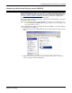
Configuring the Network Settings on the ATS-XPE 3. Highlight Internet Protocol (TCP/IP) and select Properties. 4. Configure the network connection to your network as needed, and select Ok. The default network settings for the adapters are: Adapter#1 IP Address 192.168.250.251 Subnet mask 255.255.255.0 Gateway 192.168.250.1 Adapter#2 IP Address 192.168.255.252 Subnet mask 255.255.255.0 Gateway 192.168.255.
Changing the Default Computer and Workgroup Names Changing the Default Computer and Workgroup Names If you plan on installing more than one ATS-XPE on your network, you must change the default computer name. 1. Right-click My Computer, select Properties and the Computer Name tab. 2. Select the Change button and enter the new computer name. Note: Use standard characters (A-Z, a-z), digits (0-9), and hyphens.
Changing the Default Computer and Workgroup Names 3. Optionally, select the More... button to enter the primary DNS suffix of this computer. 4. Optionally, select Domain to enter a domain name or change the default name of the Workgroup. 5. After completing all changes, select the Ok button. 6. Select Ok to close the popup message.
Starting Routing and Remote Access Services 7. Select the Ok button to close the System Properties window. 8. Select Yes to restart the system now. Starting Routing and Remote Access Services Use the following procedure if you want to enable the Routing and Remote Access service. You must enable this service before you can configure dial-in. 1. Access the Computer Management console, open the Services folder, right-click Routing and Remote Access, and select Properties.
Starting Routing and Remote Access Services 2. Select Automatic in the Startup type drop list and Apply. 3. Select the Start button and Ok to close.
Setting Up Dial-In 4. To configure remote desktop use, select the Log On tab, Allow service to interact with desktop, and Ok. 5. Close the Computer Management console. Setting Up Dial-In Use the following procedure if you want to enable dial-in on the ATS-XPE. The modem must be installed and configured before configuring dial-in. You must start the Routing and Remote Access service before an Incoming Connections entry appears in the Network Connections control panel.
Setting Up Dial-In 3. Select the Users tab, check the user (or users) that you want to allow dial-in access. 4. To set up callback capabilities for a user, highlight the user name, select Properties, and the Callback tab.
Setting Up Dial-In 5. If you are not using DHCP, select the Networking tab, highlight Internet Protocol (TCP/IP) and select Properties. 6. Check Allow calling computers to specify its own IP address or specify an IP address and select Ok.
Setting Up Dial-In 7. If necessary, select the Properties button to configure Call Preferences or Data Connection Preferences on the General tab or Terminal Window usage or Hardware Settings on the Advanced tab. 8. Select the Ok button on the Incoming Connections Properties screen after completing the set up procedures.
Setting Up Remote Desktop Access Setting Up Remote Desktop Access Remote Desktop is installed and configured on the ATS-XPE so that administrators can control the ATS-XPE (host) from a remote location through a modem or a network connection. See the Installation and Configuration Guide to enable remote users that do not have administrative permissions. You may need to install Remote Desktop on a Windows XP client or Terminal Services on a Microsoft client with an operating system previous to Windows XP.
Setting Up Remote Desktop Access This page was intentionally left blank for double-sided printing 20 Installation and Setup
Managing Files on the ATS-XPE You can share the ATS-XPE and use Windows Explorer to access or move files or applications to or from any remote system. In addition, you may want to use Remote Desktop (called Terminal Services in operating systems previous to Windows XP) to control the ATS-XPE from a remote (client) system. Note: Compact flash technology does not support an unlimited number of writes. Use the compact flash to store applications but avoid using it for file storage.
Using Remote Desktop through the Network 3. Select the Experience tab and the appropriate connection speed. 4. Select the Connect button.
Using Remote Desktop through a Modem Using Remote Desktop through a Modem Use this procedure to initiate a Remote Desktop session. 1. If necessary, create a dial-up connection on the client to the ATS-XPE. 2. Initiate the dial-up connection to the ATS-XPE. 3. From the Start button, select Programs, Accessories, Communications, Remote Desktop. 4. Complete the Logon settings information on the General tab, 5. Select the Experience tab and select the appropriate modem line.
Using Remote Desktop through a Modem 6. Select the Connect button.
PC104 RocketPort Option The PC104 RocketPort serial card is optional in the DeviceMaster ATS-XPE. Note: This option can only be installed by Comtrol. This section discusses the following topics: • PC104 RocketPort default settings. • Configuring the serial ports for your serial devices. Review Default PC104 Port Configuration (below) to determine whether you need to reconfigure any of the default settings. Note: The driver default for the ports is RS-232.
Configuring the RocketPort Serial Ports Configuring the RocketPort Serial Ports Use the following procedure if you need to reconfigure the RocketPort driver for your serial devices. 1. Access the RocketPort 8 Port Properties page through the Device Manager. a. Right-click My Computer and select Properties. b. Select the Hardware tab and the Device Manager button. c. Expand the Multi-port serial adapters selection, right-click RocketPort 8 Port, ISABUS, and select Properties. 2. Select the Main Setup tab.
Configuring the RocketPort Serial Ports 3. To change the name of the PC104 RocketPort adapter or the starting COM port number, highlight RK #2 and select Properties. a. Change the Name or the Starting COM Port number. • COM1 is assigned to the CONSOLE port. • COM2 is assigned to the AUX A port. • COM3 is assigned to the optional PCMCIA Ethernet/Modem card. Note: The default starting COM port number is COM4. b. Select Ok to return to the Main Setup screen.
Configuring the RocketPort Serial Ports 4. Highlight the port for which you want to configure COM port characteristics and select Properties. Note: COM4 is the default starting COM port. - COM1 is assigned to the CONSOLE port. - COM2 is assigned to the AUX A port. - COM3 is assigned to the optional PCMCIA Ethernet/Modem cards. a. Change the communications mode to match the device you plan to connect. b. If necessary, set an Override and lock baud rate to value.
Configuring the RocketPort Serial Ports 5. If you selected RS-485 as the communications mode, highlight the port, select Properties and then the RS-485 tab. a. Check the Check the RS485 Port Properties - RTS Toggle RTS Low box to toggle the RTS output signal low during data transmission. If this box is not checked, RTS is toggled high (asserted) during data transmission. b.
RocketPort Serial Port Connectors RocketPort Serial Port Connectors The following subsections illustrate the pinouts for the quad- and octacable connector types and how to build loopback plugs for testing serial ports. DB9 Connectors This illustrates the pinouts for DB9 quad- or octacables.
Building Additional DB25 Loopback Plugs Building Additional DB25 Loopback Plugs Loopback connectors are DB25 female serial port plugs that you can use to test serial ports. The ATS-XPE is shipped with a a single loopback plug (RS-232/422) that corresponds to your quad- or octacable type. Note: You can run loopback tests with Test Terminal. Wire the following pins together to build additional plugs or replace a missing RS232 loopback plug: . .
Building Null-Modem Cables Use the following figure if you need to build a null-modem cable. A null-modem cable is required to connect the CONSOLE port to a PC COM port or to connect DTE devices.
Troubleshooting Serial Ports Troubleshooting Serial Ports The following subsections discuss the following utilities that are installed on the ATS-XPE: Using Test Terminal • Test Terminal program (wcom32.exe), which can be used to troubleshoot communications on a port-by-port basis. • Port Monitor program (portmon.exe), which checks for errors, modem control, and status signals (Using Port Monitor on Page 35). In addition, it provides you with raw byte input and output counts.
Testing a Comtrol Port Testing a Comtrol Port Use the following procedure to test the RocketPort PC104 serial port. 1. Place a loopback plug on the COM port you are testing. Make sure all connectors are seated firmly and that the loop button is off. Note: Test terminal works for RS-232 and RS-422 mode. To build loopback plugs, see Building Additional DB9 Loopback Plugs on Page 30, Building Additional DB25 Loopback Plugs on Page 31, or Building Additional RJ45 Loopback Plugs on Page 31. 2.
Using Port Monitor The right most light is the loop indicator: If this is on, the COM port internal loopback feature is activated and any information or code entered in the terminal window loops back through the COM port circuitry. If this is off, the COM port internal loopback is deactivated, and any information or code entered in the terminal window is sent out of the port. Using Port Monitor The Port Monitor program (portmon.
Changing Screen Appearance Changing Screen Appearance While Port Monitor is running, there are a number of commands and controls that change the appearance of the screen. Desired Change Procedure Change the monitor window font. Select Font from the Edit menu. Change width of a single column. Left-click on the column separator (vertical) line and drag it to the desired width. Change column placement. Left-click in the middle of the column you want to move and drag it to the desired location.
Report Configuration Report Configuration To configure reports, select Config from the Edit menu. The Single report options cover all ports and are overwritten each time the reports are generated. The Multiple report options generate a separate report for each port, and each report file is appended each time the report is generated. For Hour reports, use the Single and Multiple drop lists to select whether you are generating single or multiple reports, or both.
Port Monitor Variables All Port Monitor calculations are saved at program exit and on the hour in a binary file named calcs.dat. This enables you to halt Port Monitor execution without losing accumulated data. Port Monitor also creates a \REPORTS directory. All hourly and daily reports are saved in this directory, under the following names: • hall.txt — hourly single report • dall.txt — daily single report • hcomx.txt — hourly multiple reports, where x is the port number • dcomx.
Port Monitor Variables Variable PC104 RocketPort Option Description TxDayCnt Transmit bytes count sent in the last day. RxMinCnt Receive bytes count sent in the last minute. RxHourCnt Receive bytes count sent in the last hour. RxDayCnt Receive bytes count sent in the last day. TxMinCntWrk Transmit bytes count sent in this minute. TxHourCntWrk Transmit bytes count sent in this hour. TxDayCntWrk Transmit bytes count sent in this day. RxMinCntWrk Receive bytes count sent in this minute.
Using Peer Tracer Using Peer Tracer The Peer Tracer program (peer.exe) is specifically designed to view the internal operations of NS-Link for the purpose of troubleshooting communications on Windows NT systems. Peer enables you to see: • Receive and transmit data • Internal driver event traces • Advanced configuration and status information Like Test Terminal, Peer acts as a simple terminal session, and is used to send and receive text information to and from NS-Link.
Log Functions Log Functions All logging functions are found under the File menu. To start keeping a log, select Log to Disk from the File menu. The other options on this menu are View Disk Log, Clear Disk Log, Clear Screen, and Exit. Compact flash technology does not support an unlimited number of writes. Use the compact flash to store applications but avoid using it for file storage. If your application generates files, save the files on a remote system.
Device Driver and OS Capabilities and Limitations Device Control Block Settings 42 Status fInX, fOutX Supported fNull Supported fParity Supported fOutxCtsFlow Supported fRtsControl RTS_CONTROL_DISABLE, RTS_CONTROL_ENABLE, RTS_CONTROL_HANDSHAKE, RTS_CONTROL_TOGGLE fTXContinueOnXoff Supported as always TRUE Parity EVENPARITY, NOPARITY, or ODDPARITY StopBits ONESTOPBIT or TWOSTOPBITS XonChar, XoffChar Supported PC104 RocketPort Option
Certified PCMCIA Adapters This section discusses configuration issues for Comtrol certified PCMCIA options. Comtrol Certified PCMCIA Devices The ATS-XPE supports the following PCMCIA devices. • Any standard PCMCIA to Compact Flash adapter • Linksys Wireless PC Card (WPC11) • Linksys EtherFast 10/100 + 56K Modem PC Card (PCMLM56) Note: The ATS-XPE PCMCIA option supports two Type II PCMCIA slots or one Type III slot, which is installed at the factory.
Linksys Wireless PC Card (WPC11) 2. Select Don’t search. I will choose the driver to install and Next. 3. Select Network adapters from the Common hardware types list and Next. 4. Select LINKSYS Corporation from the Manufacture list, Instant Wireless Network PC CARD from the Network Adapter list, and Next.
Linksys Wireless PC Card (WPC11) 5. Select Yes to the Update Driver Warning message. 6. Select Finish. 7. Open the Network Connections control panel, right click Wireless Network Connection from LAN or High-Speed Internet, and select View Available Wireless Networks.
Linksys Wireless PC Card (WPC11) 8. Highlight the network to which you want to connect. 9. If requested, enter the appropriate information in the Network key and Confirm network key fields, and select Connect. 10. Right-click the Wireless Network Connection and select Properties.
Linksys EtherFast 10/100 + 56K Modem PC Card (PCMLM56) 11. To configure the card exclusively for a specific network, select View Available Wireless Networks. 12. Highlight the appropriate network connection and Advanced. 13. Select Access point (infrastructure) networks only and Close. 14. Select Ok to close the Wireless Network Connection Properties window and close the Network Connections control panel. 15.
Linksys EtherFast 10/100 + 56K Modem PC Card (PCMLM56) This page was intentionally left blank for double-sided printing.
Installing Serial Devices Overview The COM ports provided by the SERIAL PORTS 1-8 can support any asynchronous serial modem for use by any application that uses TAPI. There is a remote possibility that connecting a peripheral using the wrong configuration (RS-232 device connected to a RS-422 configured port) could damage the peripheral. Configure each serial port specifically for the peripheral that will be connected prior to connecting the peripheral to the ATS-XPE.
Installing Modems 4. Select Don’t search. I will choose the driver to install and Next. 5. Select Modems from the Common hardware types list and Next. 6. Select Have Disk and Next.
Installing Modems 7. Browse to the location of the driver for your modem and select Open. 8. Select Ok. 9. Select Next.
Installing Modems 10. Select Continue Anyway. 11. Select Finish. In some installations you may get the following message, so you may need to verify that the modem installed properly through the Device Manager. 12. See Starting Routing and Remote Access Services on Page 13 and Setting Up Dial-In on Page 15 to complete modem configuration.
Troubleshooting and Technical Support This section contains troubleshooting information for your Comtrol device. You should review the following subsections before calling Technical Support because they will request that you perform many of the procedures or verifications before they will be able to help you diagnose the problem.
Enabling the Event Viewer Enabling the Event Viewer The Windows Event Viewer has been disabled in the ATS-XPE to prevent excess file logging. Compact flash technology does not support an unlimited number of writes. We recommend using the compact flash to store applications but avoid using it for file storage. Use the following procedure if you wish to enable the Event Viewer. 1. Access the Computer Management console, open the Services folder, right-click Event Log, and select Properties.
Using the Recovery CD 2. Select Manual in the Startup type drop list and Ok. 3. Close the Computer Management console. Using the Recovery CD Comtrol ships a Recovery CD with each ATS-XPE system. You can use the Recovery CD to: • Reflash the compact flash in the event that the Windows XP Embedded system becomes corrupt. • Recover the default image to the ATS-XPE compact flash. • Replace the existing flash with a larger flash.
Customer Support Policy To use the Recovery CD, you will need the following: • • A PC with a Windows operating system and a CD-ROM that supports bootable CDs. One of the compact flash adapters or readers: - • IDE Note: The IDE flash adapter must be a master with no other devices on that channel because the recovery process is propagated to all devices on the channel. USB PCMCIA A compact flash. Use the following procedure to recover the default ATS-XPE image onto a compact flash. 1.
Technical Support Technical Support If you need technical support, contact Comtrol using one of the following methods. Contact Method Corporate Headquarters Comtrol Europe FAQ/Online http://support.comtrol.com/support.asp Downloads ftp://ftp.comtrol.com/Dev_Mstr/ATS/XPE Email support@comtrol.com support@comtrol.co.uk Web site http://www.comtrol.com http://www.comtrol.co.
Repair and Return Policy This page was intentionally left blank for double-sided printing 58 Troubleshooting and Technical Support
Appendix A. Connectors This section contains information about the standard connectors on the ATS-XPE. For connector information for the optional SERIAL PORTS 1-8 connector, see the section that discusses the PCMCIA option. VGA Connector This table illustrates the 15-pin female VGA connector pinouts.
USB Interfaces USB Interfaces The USB interfaces provide plug and play for up to 127 external devices. Pin Description Pin Description 1 USBVCC1 2 D1F- 3 D1F+ 4 GND 5 USBVCC2 6 D2F- 7 D2F+ 8 GND 9 GND 10 GND Compact Flash Disk Connector This table illustrates the compact flash connector pinouts.
AUX A and CONSOLE Port Connectors AUX A and CONSOLE Port Connectors This table illustrates the DB9 pinouts for the AUX A and CONSOLE connectors. Pin Signal Pin Signal Pin Signal 1 CD 4 DTR 7 RTS 2 RxD 5 Ground 8 CTS 3 TxD 6 DSR 9 RI PARALLEL Port This table illustrates the DB25 PARALLEL pinouts.
Serial Ports 1-8 Connector (Optional) Serial Ports 1-8 Connector (Optional) This table lists the pinouts for the DB78 connector.
Appendix B. Specifications and Notices This section discusses the following topics: • Product specifications - • Electromagnetic compliances Environmental condition specifications Hardware specifications Technical specifications Default operating system configuration FCC Part 15 Class A notices Product Specifications The following subsections provide a variety of information about the DeviceMaster ATS-XPE.
Environmental Condition Specifications Environmental Condition Specifications The following table illustrates environmental condition specifications for the DeviceMaster ATS-XPE.
Technical Specifications Technical Specifications This subsection lists the DeviceMaster ATS-XPE technical specifications. • Compact flash (512 MB) with pre-configured Windows XP operating system. See Default Operating System Configuration on Page 66 for detailed information. • NS GXLV/GX1-300 MMX 32-Bit x86 Processor that supports the Intel® MMX instruction set extension for the acceleration of multi media applications.
Default Operating System Configuration Default Operating System Configuration The following list is a baseline operating system configuration for the ATS-XPE. For information about the operating system, see Windows XP Embedded on the Microsoft web site at: http://www.microsoft.
Default Operating System Configuration Direct memory access controller System timer System CMOS/real time clock System speaker Numeric data processor System board Motherboard resources PCI bus ISAPNP Read Data Port ISA Plug and Play bus Comtrol hardware controller Comtrol display controller Plug and Play Software Device Enumerator Universal Serial Bus controllers Compaq PCI to USE Open Host Controller USB Root Hub Software System User Interface Shells Explorer Shell Windows Shell Accessories/Communications
Default Operating System Configuration Shell Core Registry Data Shell Explorer Registry Data (Pro) Shell Explorer Registry Data Shell Group Conversion Registry Data Shell Hyperterminal Registry Data Shell Legacy Registry Data Shell Namespace Extensions Shell Namespace Registry Data Shell Notepad Registry Data Shell Paint Registry Data Shell Utilities Registry Data Standard Start Menu Shortcuts System Control Panel Task Manager Tray Icon Add/Remove Support USB User Interface User Interface Core Users Contro
Default Operating System Configuration Remote Registry Service Session Manager (Windows Subsystem) Setup & Safe Mode VGA System Cloning Tool System Event Notification Service Volume Shadow Copy Service Application Support Application Compatibility Core COM Base COM+ Services Distributed Transaction Coordinator DOS Windows on Windows Support HTML Help Engine Jet Database Engine Jet Database OLEDB Support Microsoft Data Access Components (MDAC) Microsoft Foundation Class Library (Legacy) Microsoft Foundation
Default Operating System Configuration Security Infrastructure Certificate Request Client & Certificate Autoenrollment Certificate User Interface Services Credential Management User Interface Cryptographic Network Services Cryptographic Service Providers Kernel Mode Crypto Driver for RSA Key Manager Netlogon/Net Join RPC Local Support RPC Remote Secure RPC over Kerberos Secure RPC over Negotiate Secure RPC over NTLM Security Accounts Manager Server Library Smart Card Cryptographic Service Providers Smart C
Default Operating System Configuration Mapi32 Libraries Ndisuio Inf Netbios Driver Netbrdgs Inf NetDav Inf Netmscli Inf Netrib Inf Netrasa Inf Netrass Inf Netrast Inf Netserv Inf Netshell Nettcpip Inf Network Diagnostics Network Performance Counters Network Routing Netwzc Inf Other TCP/IP Services Routing Common Files SDP Blob Parser SNMP SMB Redirector TAPI 2.
Default Operating System Configuration GDI+ 1.0.0.0 GDI+ 1.0.10.
Default Operating System Configuration NLS: Core Files NLS: Locale Map Ids NLS: Time Zones Accessibility Infrastructure Accessibility Core Default Component Settings Hardware Devices Computers Standard PC System Identification Computer name: XPE4-8 Registered owner: OEM Registered organization: OEM Pagefile no pagefile support Power Management Settings Power mgmt.
Default Operating System Configuration Management Infrastructure Lightweight Directory Access Protocol (LDAP) Default LDAP Connection Signing: Connections signed if possible International Regional and Language Options User interface language: English Standards and formats: English US Default input language: English US Language for non-Unicode programs: English US Geographical location: United States Security Infrastructure Windows Logon Show Friendly Winlogon Show Welcome to Windows screen before Winlogon
Notices Notices Radio Frequency Interference (RFI) (FCC 15.105) This equipment has been tested and found to comply with the limits for Class A digital devices pursuant to Part 15 of the FCC Rules. This equipment generates, uses, and can radiate radio frequency energy, and if not installed and used in accordance with the instruction manual, may cause harmful interference to radio communications. However, there is no guarantee that interference will not occur in a particular installation.
Important Safety Information This page was intentionally left blank for double-sided printing.
Appendix C. Default System Values The following section provides information for changing default configuration of the DeviceMaster ATS motherboard. In most cases, it will not be necessary to reconfigure the motherboard. Note: The information in this document is for reference only. The DeviceMaster ATS is pre-configured before shipment. You may want to access the motherboard to perform the following tasks: • Change the watch-dog timer settings. • Clear CMOS setup.
Accessing the Motherboard 78 Appendix C.
Clearing the CMOS Setup Clearing the CMOS Setup If you need to clear the CMOS Setup. For example, if you forgot the password you should clear the setup and then set the password again. You should close the JP1 jumper for about 3 seconds and then open it again. To set the CMOS back to normal operation mode, open JP1. JP1 Description 1-2 Normal Operation. 2-3 Clear CMOS Setup. Note: Use the screenshots in Changing BIOS Configuration on Page 83 to reconfigure the factory default BIOS settings.
Changing the Watch-Dog Timer Three I/O ports control the Watch-Dog Timer and are accessed using the addresses defined in the following table. Hex Address Read/Write Description 443H Write Set Watch-Dog Time period 443H Read Enable and refresh the Watch-Dog Timer. 843H Read Disable the Watch-Dog Timer. Prior to enabling the Watch-Dog Timer, the user has to define the time interval to be used. The timer interval is defined by writing a value to address 443H.
System I/O Address Map MOV DX, TIMER_START IN AL, DX. ;;RESTART COUNTER ;;ADD YOUR APPLICATION HERE CMP JNE MOV IN EXIT_AP, 0 W_LOOP DX, TIMER_STOP AL, DX ;;EXIT AP System I/O Address Map This table illustrates the system I/O address map for the ATS. I/O Address Appendix C.
First MB Memory Map First MB Memory Map This table illustrates the first MB memory map. Address 82 Description F000h-FFFFh System ROM D800h-EFFFh Unused C800h-D7FFh Ethernet ROM C000h-C7FFh Expansion ROM B800h-BFFFh CGA/EGA/VGA text B000h-B7FFh Unused A000h-AFFFh EGA/VGA graphics 0000h-9FFFh Base memory Appendix C.
Appendix D. Changing BIOS Configuration This section discusses using the BIOS to change the system defaults. The DeviceMaster ATS-XPE uses the AWARD PCI/ISA BIOS for system configuration. The AWARD BIOS setup program is designed to provide maximum flexibility in configuring the system by offering various options which may be selected to meet your requirements. Note: The information in this appendix is for reference only. The DeviceMaster ATS-XPE is pre-configured before shipment.
Standard CMOS Setup Standard CMOS Setup The Standard CMOS Setup screen is used for basic hardware system configuration, such as the Date and Time settings. This figure illustrates the DeviceMaster ATS-XPE factory defaults. Use the following procedure to change the system date. 1. Press either the Arrow or key on your keyboard to select one of the fields (Month, Date or Year). 2. Press either or to increase or decrease the value of that field. 3.
Chipset Features Setup Chipset Features Setup The Chipset Features Setup screen primarily controls the board's chipset and is used to change the chipset configuration. This figure illustrates the DeviceMaster ATS-XPE factory defaults. USB Legacy Support Enabled : Disabled Note: Improperly changing these default settings can result in an unstable system. Power Management Setup The Power Management Setup screen helps you handle the ROCKY-568SEV board’s green function.
PNP/PCI Configuration PNP/PCI Configuration This menu is used to assign IRQ numbers to your PNP/PCI devices manually. This figure illustrates the DeviceMaster ATS-XPE factory defaults. Manual Used MEM base addr 86 : N/A • PNP OS Installed: If you install a Plug and Play operating system (OS), the OS will reassign the interrupt even if you choose Yes for this option.
Load BIOS Defaults Load BIOS Defaults If you choose to activate the Load BIOS Defaults menu and then answer Y to load the Load BIOS Defaults prompt, the AWARD defaults load with the exception of the Standard CMOS setup. Note: If you load the default BIOS, you will change Comtrol™ Corporation’s default settings and may experience unreliable results and an unstable platform. Select N to abort this screen. Load Setup Defaults If you select Y to this field, the Setup Defaults load except Standard CMOS SETUP.
Integrated Peripherals Integrated Peripherals This option is used to assign Onboard I/O, IRQ, DMA, etc. This figure illustrates the DeviceMaster ATS-XPE factory default settings. • Multiple Monitor Support -- No Onboard, PCI first, M/B first Use to select the primary VGA for multiple monitor support in Windows. • Video Memory Size -- 4.0M Use to select the size of video memory.
SVGA Setup Introduction SVGA Setup Introduction The DeviceMaster ATS-XPE is equipped with an on-board LCD/VGA interface. The following subsections discuss its specifications and features. Chipset The DeviceMaster ATS-XPE uses a Cyrix™ CX5530 chipset as its SVGA controller.
SVGA Setup Introduction This page was intentionally left blank for double-sided printing. 90 Appendix D.
Appendix E. Changing the WatchDog Timer The hardware watch-dog timer is not supported by the installed Linux kernel. However, it may be accessed directly by user applications if desired. The Watch-Dog Timer is a device used to ensure that standalone systems can reset themselves and recover from catastrophic conditions that cause the CPU to hang or crash. The Watch-Dog Timer is a countdown timer that will reset the CPU when it times out. The Watch-Dog Timer is enabled by reading port 443H.
Changing the WatchDog Timer The Watch-Dog Timer is activated by reading the value at address 443H. To ensure that a reset condition does not occur, the timer must be periodically reset to restart the countdown at the beginning of the defined interval before the time out period has expired. This is achieved by first disabling the timer by reading address 843H and then re-enabling it by reading the value at 443H before the timer reaches zero. Refer to the example of the assembly program below.
Index Numerics 10/100M bps Ethernet 65 A accessing the motherboard 77 agency notices 75 air temperature 64 altitude 64 AUX A port default baud 64 installing modems 49 pinouts 61 B baud rates default 64 BIOS 65 changing configuration 83–89 building DB25 loopback plugs 31 DB9 loopback plugs 30 null-modem cable 32 RJ45 loopback plugs 31 RS-485 test cable 31 straight-through cable 32 C cables build null-modem 32 build RS-485 test cable 31 build straight-through 32 certified PCMCIA options 43 changing BIOS conf
Index enabling dial-in 15 Event Viewer service 54 Routing and Remote Access service 13 environmental conditions 64 Ethernet connectors 59 LEDs 7 network configuration 9 PCMCIA card 47 type 65 wireless PCMCIA option 43 Event Viewer service enabling 54 F FAQs 57 fax Technical Support 57 FCC rules 75 file management 21–24 files compact flash usage 21 first MB memory map 82 H hardware ring indicator emulation 28 heat output 64 humidity 64 I I/O address map 81 immunity 63 installation hardware 6 PCMCIA wireless
Index PC104 DB25 connectors 30 DB78 connector 62 DB9 connectors 30 driver capabilities 41 driver control 64 port configuration 26 RJ45 connectors 31 RocketPort daughter card 65 RocketPort option 25–42 troubleshooting ports 33–41 PCMCIA connecting to 6 Linksys Wireless PC card WPC11 43 PCMCIA Ethernet and modem card 47 PCMCIA port default baud 64 slot type 65 supported adapters 43 Peer Tracer 40 phone Technical Support 57 Port Monitor 35 power consumption 64 input 64 printer default 61 processor 65 product
Index 96 Index