
Manual

Chapter 5. Installation and Testing
Configuration Mode Description File
RAM [RAM] RedBoot running from
RAM with RedBoot in the
flash boot sector.
redboot_RAM.ecm
Initial Installation Method
A device programmer should be used to program a socketed FLASH part (AMD 29F040). The board as delivered
is configured for a 512K EPROM. To install a FLASH ROM, Jumpers J30, J31 and J36 need to be changed as
described in the board’s User Manual.
Special RedBoot Commands
None.
Memory Maps
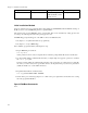
RedBoot sets up the memory map primarily as described in the board’s User Manual. There are some minor
differences, noted in the following table:
Physical Virtual Resource
Addresses Addresses
00000000-01FFFFFF 80000000-81FFFFFF Base SDRAM (cached)
00000000-01FFFFFF A0000000-A1FFFFFF Base SDRAM (uncached)
0C000000-0C0BFFFF AC000000-AC0B0000 PCI IO space
0F000000-0F0001FF AF000000-AF0001FF VRC4375 Registers
1C000000-1C0FFFFF BC000000-BC0FFFFF VRC4372 Registers
1C100000-1DFFFFFF BC100000-BDFFFFFF PCI Memory space
1FC00000-1FC7FFFF BFC00000-BFC7FFFF FLASH ROM
80000000-8000000D C0000000-C000000D RTC
8000000E-80007FFF C000000E-C0007FFF NVRAM
81000000-81FFFFFF C1000000-C1FFFFFF Z85C30 DUART
82000000-82FFFFFF C2000000-C2FFFFFF Z8536 Timer
83000000-83FFFFFF C3000000-C3FFFFFF 8255 Parallel port
87000000-87FFFFFF C7000000-C7FFFFFF Seven segment display
NOTE: By default the VRC4375 SIMM control registers are not programmed since the values used must
depend on the SIMMs installed. If SIMMs are to be used, correct values must be placed in these registers
before accessing the SIMM address range.
NOTE: The allocation of address ranges to devices in the PCI IO and memory spaces is handled by the eCos
PCI support library. They do not correspond to those described in the board User Manual.
153