
User guide

DeviceMaster FreeWire Installation and User Guide: 2000412 Rev. D Hardware Installation - 7
Hardware Installation
This section discusses the following hardware related topics in addition to the
hardware installation procedure:
• Device Descriptions (below)
• LED Indicators
on Page 9
• Reset Button Functions
on Page 9
• Factory Default Settings
on Page 10
• Port Parameters
on Page 11
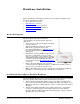
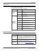
Device Descriptions
The DeviceMaster FreeWire includes the
components that are discussed in the following
subsections:
• Power connector – The power supply cable plugs
into this connector.
• LED status indicators (Power, 10, and 100) –
Indicate the operational states of the
DeviceMaster FreeWire. See LED Indicators
on
Page 9 for detailed LED status light
descriptions.
• Reset button – Pressing the Reset button for less
than five seconds prints a test page (if the
device is connected to a serial printer). Pressing
and holding the Reset button for more than five
seconds resets the DeviceMaster FreeWire to
factory default settings (Reset Button Functions
on Page 9).
• 10/100 – The RJ45 Ethernet port is used for
connecting the DeviceMaster FreeWire to an Ethernet card, hub, router, or
other wired access point for network access.
• RS232 – The DB9 serial port can be configured to connect the DeviceMaster
FreeWire to a serial device that uses the RS-232 serial interface.
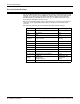
Installing the DeviceMaster FreeWire Hardware
The DeviceMaster FreeWire can be wall mounted, set on the desktop, or mounted
using the optional DIN rail kit available from Comtrol Corporation.
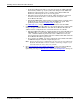
1. Write down the 12-digit MAC (Media Access Code) address printed on the
label located on the bottom of the DeviceMaster FreeWire (for example: 00 C0
4E 27 00 00). You may need this number in order to configure the DeviceMaster
FreeWire.
2. Plug the DeviceMaster FreeWire power supply adapter into a suitable AC
receptacle, and then plug the power supply cable into the DeviceMaster
FreeWire. The DeviceMaster FreeWire will run through a sequence of power-
up diagnostics for a few seconds.